Electrical connector

a technology of electrical connectors and connectors, which is applied in the direction of coupling contact members, coupling device connections, coupling parts, etc., can solve the problems of difficult to reduce the size of the electrical connector in a width direction, the shape of the mold and the manufacturing process is complicated, and it is difficult to connect the flat conductive member to the electrical connector. , to achieve the effect of reducing the size of the electrical connector

Inactive Publication Date: 2007-11-01
HIROSE ELECTRIC GROUP
View PDF4 Cites 9 Cited by
  • Summary
  • Abstract
  • Description
  • Claims
  • Application Information

AI Technical Summary

Benefits of technology

[0032]According to an embodiment of the present invention, when the flat conductive member is attached to the electrical connector, it is possible to obtain the electrical connector with the flat conductive member.
[0033]As described above, in the embodiments of the present invention, while maintaining a flat plate surface of a metal plate, the metal plate is processed to form the engaging portion of the metal member. The metal member is disposed on the housing such that the metal member is situated in parallel to the terminals. It is arranged that the engaging portion engages the engagement portion of the flat conductive member. Accordingly, it is possible to easily produce the electrical connector without bending a metal plate. Further, it is possible to limit a size of the electrical connector in the width direction thereof according to the plate thickness of the metal member, thereby reducing a size of the electrical connector in the width direction, or making it possible to increase the number of the terminals.

Problems solved by technology

Accordingly, it is difficult to connect the flat conductive member to an electrical connector.
Further, it is difficult to reduce a size of the electrical connector in a width direction thereof.
Accordingly, a shape of a mold and a manufacturing process tend to be complicated.
Further, the lock arm is formed of a resin same as that of the housing, thereby reducing strength thereof.
Accordingly, it is difficult to produce the hook member.

Method used


Image

  • Electrical connector
  • Electrical connector
  • Electrical connector

Examples


first embodiment

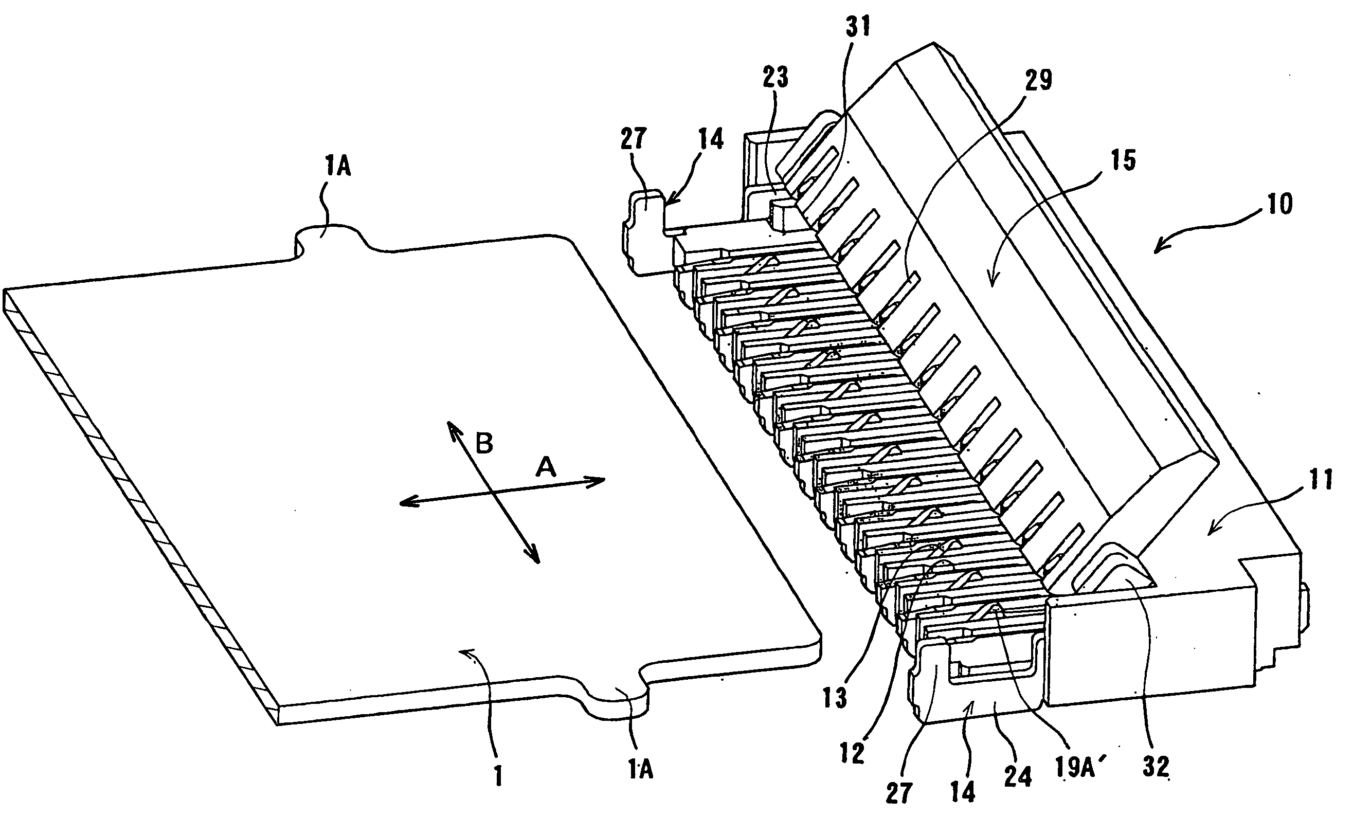
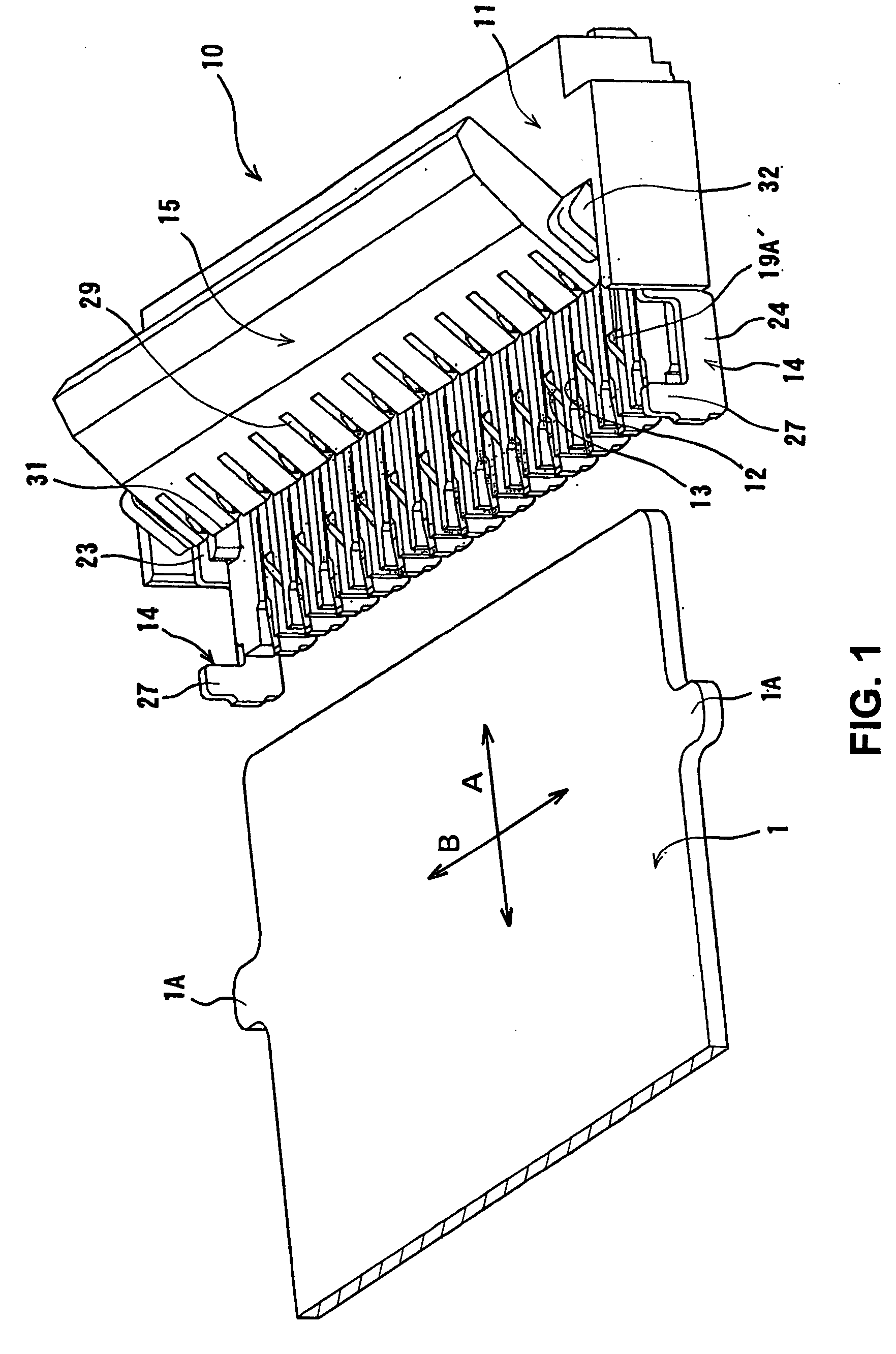
[0043]FIG. 1 is a perspective view showing an electrical connector 10 and a flat conductive member 1 to be connected to the electrical connector 10 according to the present invention. In the flat conductive member 1, a plurality of conductive members (not shown) is arranged next to each other along an arrow direction A perpendicular to an arrow direction B. Each of the conductive members is exposed at an end portion (right side in FIG. 1) of the flat conductive member 1. A reinforcement sheet is attached to an upper surface of the flat conductive member 1. Further, the flat conductive member 1 is provided with engagement portions 1A formed in an ear shape and disposed at both side edges on a distal end side of the reinforcement sheet.

[0044]In the embodiment, the electrical connector 10 to be connected to the flat conductive member 1 includes a housing 11 formed of an insulative material and arranged above a circuit board (not shown); a plurality of terminals 12 and 13 arranged on th...

second embodiment

[0072]In the present invention, in addition to the embodiment shown in FIG. 1 to 5, various modifications are possible. FIG. 6 is a perspective view showing the electrical connector 10 according to the present invention.

[0073]As shown in FIG. 6, a column portion 33 is disposed on the housing 11 inside and adjacent to the engaging portion 27 of the metal member 14 along the arrangement direction of the terminals 12 and the terminals 13. In the embodiment, the column portion 33 has a rectangular column shape, and includes an engaging surface 33A situated at a position substantially same as that of the plate thickness surface 27A of the engaging portion 27 in the front-to-rear direction, or at a position shifted forward by a distance δ with respect to the plate thickness surface 27A.

[0074]With the configuration described above, the engagement portion 1A of the flat conductive member 1 engages the plate thickness surface 27A of the engaging portion 27 and the engaging surface 33A of the...

fourth embodiment

[0081]FIG. 8 is a plan view showing the electrical connector 10 according to the present invention. In the electrical connector 10, the groove portion 26 of the metal members 14 or the engaging portion 27 are situated at positions shifted with each other in the front-to-rear direction. With this configuration, it is possible to insert only the flat conductive member 1 having the engagement portions 1A at positions corresponding the engaging portion 27. Accordingly, it is possible to prevent the flat conductive member 1 from inserting in an upside-down posture.


PUM


Abstract

An electrical connector for connecting a flat conductive member includes a plurality of terminals formed of a flat metal plate arranged on a housing in a direction perpendicular to a plate direction. Each of the terminals has a contact portion disposed at a position for receiving the flat conductive member to be inserted into a receptacle portion of the housing. A metal member having an engaging portion is attached to the housing for engaging an engagement portion of the flat conductive member, so that the flat conductive member does not come off backward. A pressing member is supported on at least one of the housing and the terminals to be rotatable. The metal member further includes an attaching portion attached to the housing. The metal member is attached to the housing such that the attaching portion is situated in parallel to a plate surface of the terminals.

Description

BACKGROUND OF THE INVENTION[0001]The present invention relates to an electrical connector. More specifically, the present invention relates to an electrical for connecting a flat conductive member and an electrical connector with a flat conductive member.[0002]Conventionally, many types of flat conductive members are used, and include a flexible print circuit board (FPC), a flat cable, and the likes. In many cases, such a flat conductive member is connected to an electrical connector attached to a circuit board.[0003]In general, the flat conductive member is integrated with fine cables or conductive members arranged in a row with a very small pitch. Accordingly, it is difficult to connect the flat conductive member to an electrical connector. Accordingly, an electrical connector may be provided with a pressing member to be rotatable. In this case, the flat conductive member is arranged above a contact portion of a terminal of the electrical connector. Then, the pressing member is ro...

Claims


Application Information

Patent Timeline
Patent Type & Authority Applications(United States)
IPC IPC(8): H01R4/50
CPCH01R12/88
Inventor OKAMURA, SEIJIMURAKAMI, HARUHIKO
Owner HIROSE ELECTRIC GROUP
Why Eureka
Try Eureka