Electrical Earthing Nut

a technology of earthing nuts and nuts, which is applied in the direction of nuts, screws, bolts, etc., can solve the problems of disconnection of glands from earth connection, arm breakage, and earth faul

Active Publication Date: 2007-11-01
PEARCE RICHARD HENRY
View PDF13 Cites 10 Cited by
  • Summary
  • Abstract
  • Description
  • Claims
  • Application Information

AI Technical Summary

Benefits of technology

[0025] An advantage of the embodiment having the raised or extended annulus is that the nut is centralised in the event it is located in an oversize hole. This feature thus ensures the nut is held stationery, by way of a

Problems solved by technology

Firstly the arm can break if bent away from the box or appliance wall.
This has resulted in a disconnection of the gland from the earth connection.
This was dangerous and could result in an earth fault.
Secondly, if the gland became loose, the connection between the washer and the gland degraded to a poor connection, which caused a high resistance path to earth.
Thirdly often the box or appliance wall was m

Method used


Image

  • Electrical Earthing Nut
  • Electrical Earthing Nut
  • Electrical Earthing Nut

Examples


Embodiment Construction

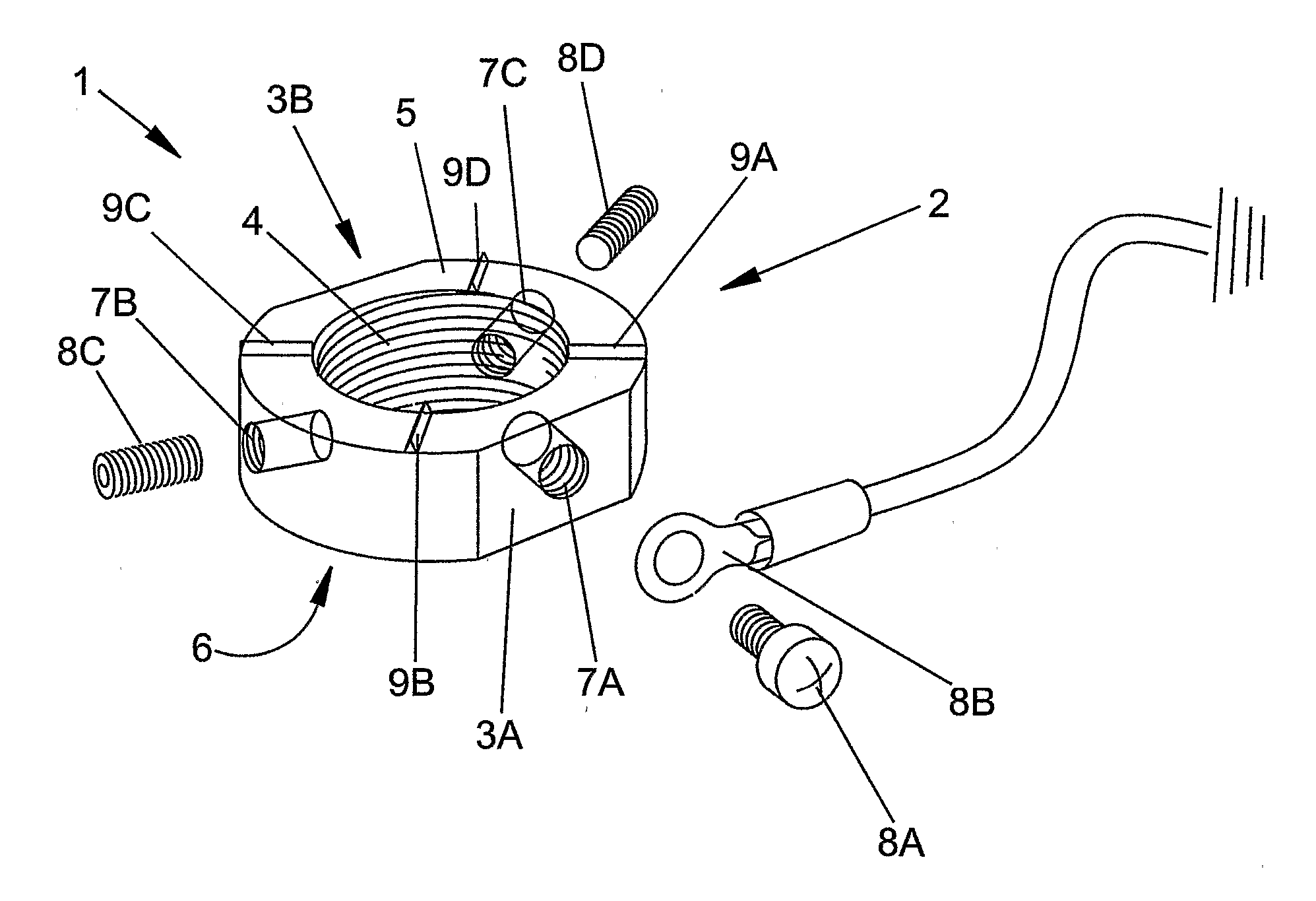
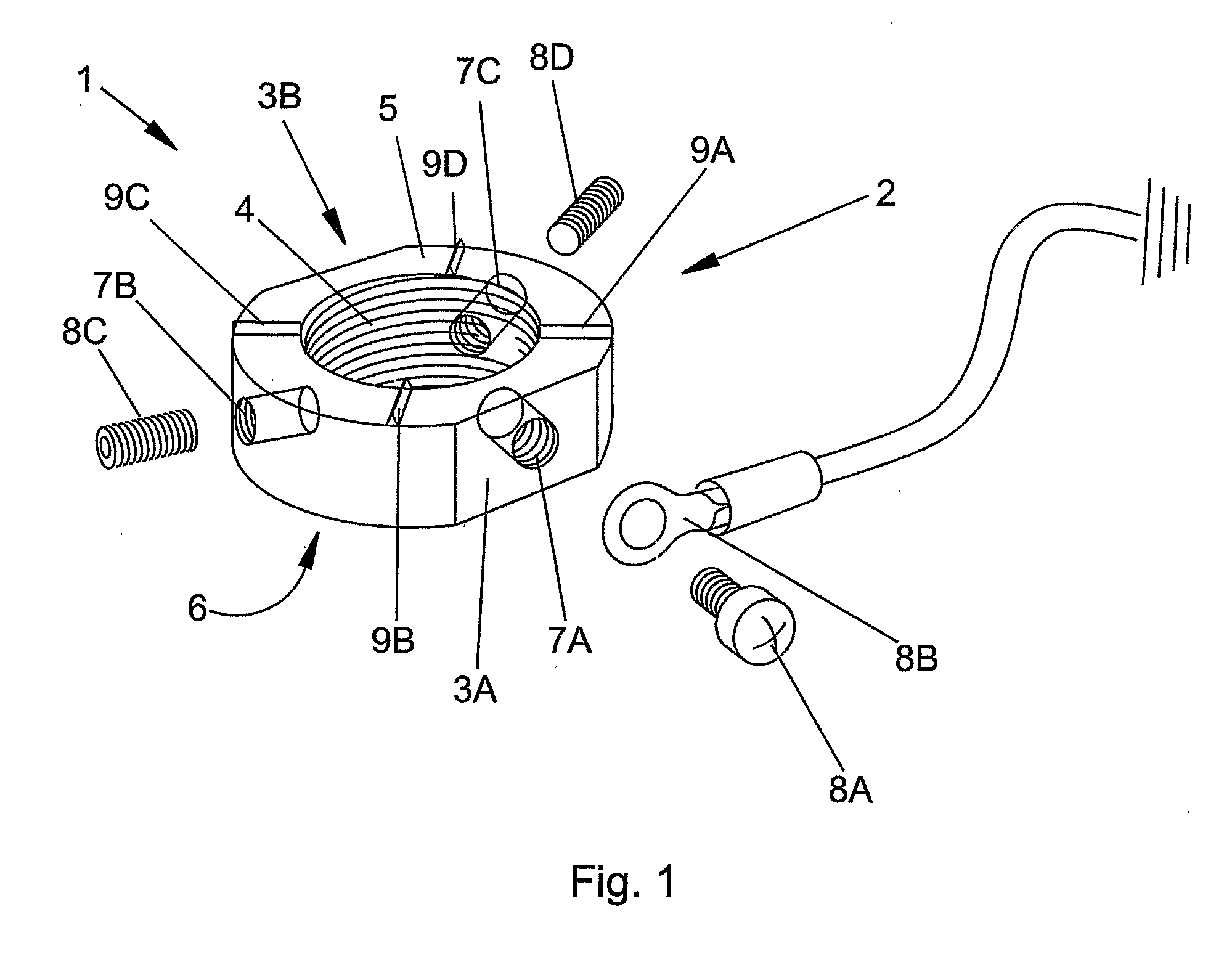
[0039] Referring to FIG. 1 there is shown an electrical earthing nut 1.

[0040] Nut 1 has an annular nut body 2 with generally circular perimeter with opposing flat portions 3A, 3B to receive a spanner or other tensioning device. Nut body 2 has an internal thread 4 to receive a threaded shaft. Nut body 2 has opposing generally planar faces 5 and 6.

[0041] Three radially spaced threaded apertures 7A, 7B, 7C extend into the nut body 2 from the nut body perimeter. Aperture 7A receives a bolt 8A and earth connector 8B with a wire leading to earth. Apertures 7B, 7C (which may be located at any position around the perimeter of the nut) each receive grub screws 8C, 8D to engage with, or bite into, a threaded shaft (not shown) on which the nut 1 is placed.

[0042] Four raised ribs in the form of teeth 9A, 9B, 9C, 9D are provided on planar face 5 to scrape or cut into a surface against which the nut is to abut. The purpose of these ribs or teeth 9A, 9B, 9C, 9D is to

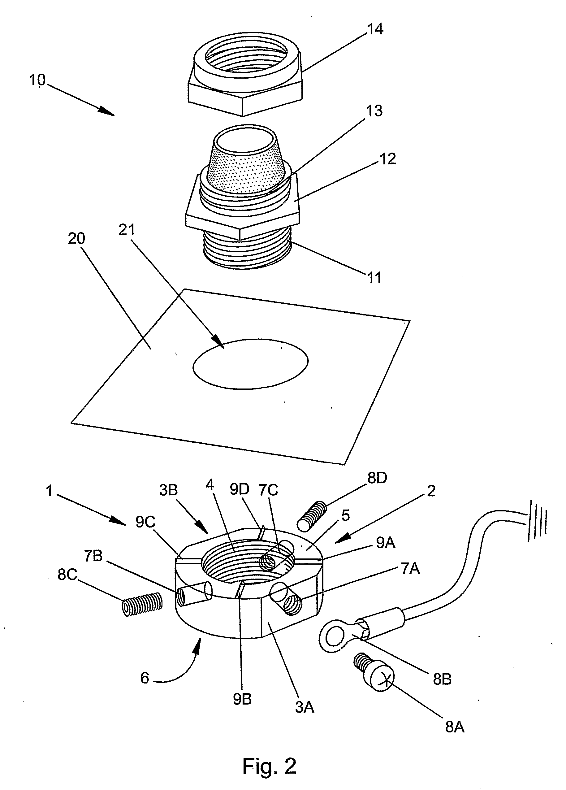
[0043] Referring now to FIG...


PUM


Abstract

The invention relates to an electrical earthing nut (1). In the past these have sometimes vibrated loose, with the result that a failsafe safety device has been rendered inoperable. The invention overcomes this problem by providing a nut (1) that has a nut body (2) having an internal thread (4) to receive a threaded shaft and an external perimeter shaped to receive a tensioning device such as a spanner. Body (2) has opposing generally planar faces 5,6. Threaded apertures (7A, 7B, 7C) are provided on the nut body to receive a bolt (8A) to secure an earth connector (8B) to the nut body (2) and grub screws (8C, 8D). Four raised ribs (9A, 9B, 9C, 9D) are provided on planar face (5) to scrape or cut into a surface against which the nut is to abut. Earthing nut (1) may be used with a cable gland.

Description

BACKGROUND [0001] The present invention relates to an electrical earthing nut. [0002] When connecting an electrical junction box or appliance to a steel wire armoured (SWA) electrical cable, it is common practice to use a SWA cable gland. Such glands have a compression fitting on one side (which is exposed) to physically clamp the steel armour wires, and a threaded shaft, which passes through the wall of a junction box or appliance. A nut is secured on the end of the threaded shaft to secure the gland to the box or appliance wall. [0003] In order to comply with safety regulations in many jurisdictions it is necessary to earth at least one end of the cable. To achieve this, a particular type of washer—known as “banjo washer”—is placed under the nut, and a bolt is then drilled through a hole in the arm of the washer to receive an earth wire employing a crimped connector. Also the arm is usually bolted through the box or appliance wall. PRIOR ART [0004] However, the aforementioned banj...

Claims


Application Information

Patent Timeline
IPC IPC(8): H01R4/38H01R4/30H01R4/64H01R11/26H02G15/04
CPCH01R4/302H02G15/04H01R11/26H01R4/646F16B39/04F16B37/00
Inventor PEARCE, RICHARD
Owner PEARCE RICHARD HENRY
Why Eureka
Try Eureka