
Water resistant l.e.d. pocket otoscope

a technology of otoscope and pocket, which is applied in the field of improved small light weight otoscope, can solve the problems of difficult to repair and the useful life of the conventional bulbs used in conventional devices, and achieves the effects of improving the useful life of the conventional bulbs used in conventional otoscopes

Inactive Publication Date: 2007-11-01
SCHMITZ JAMES DAVID
View PDF3 Cites 23 Cited by
  • Summary
  • Abstract
  • Description
  • Claims
  • Application Information

AI Technical Summary

Benefits of technology

[0009] Embodiments of the invention may further provide a pocket otoscope having an LED light source wherein the beam of light emitted from the LED light source is directed along a cylinder cavity and deflected by a mirror at a 90 degree angle through an aperture. The pocket oto

Problems solved by technology

However, difficulties have been encountered with the useful lifetime of the light bulbs and batteries used in conventional devices, as the current draw of conventional bulbs generally runs the battery of a conventional otoscope dead in a matter of hours.
Additionally, conventional bulbs used in conventional otoscopes have been shown to be easily damaged from both accidental dropping of the otoscope, as well as from the jarring and movement associated with normal operation and transportation of conventional otoscopes.

Method used


Image

  • Water resistant l.e.d. pocket otoscope
  • Water resistant l.e.d. pocket otoscope
  • Water resistant l.e.d. pocket otoscope

Examples


Embodiment Construction

[0017] The present invention generally provides an improved otoscope that utilizes a low power, durable, water resistant, LED light source.

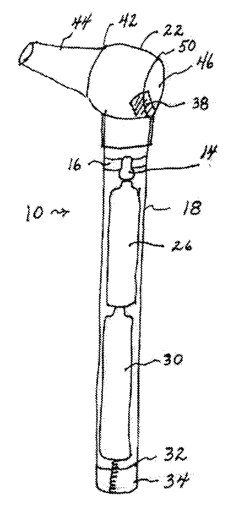
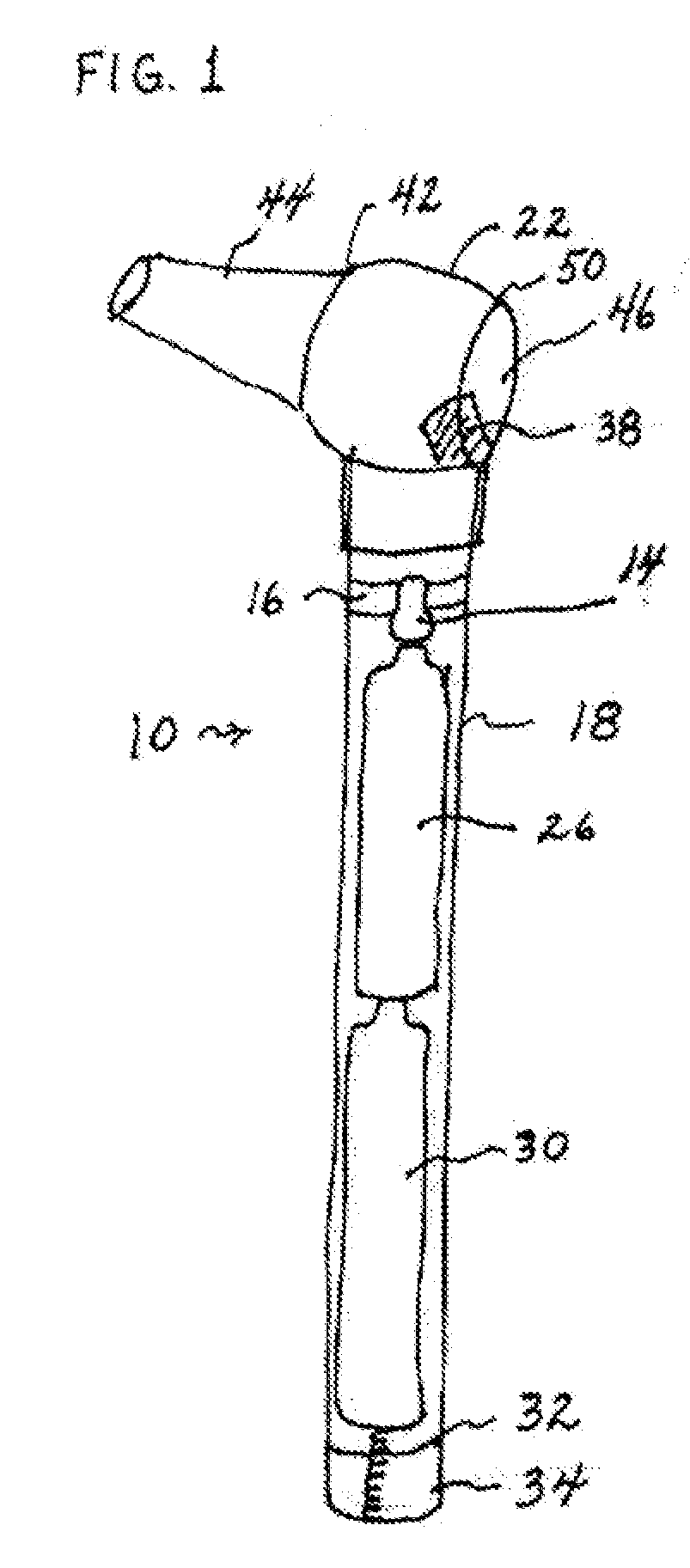
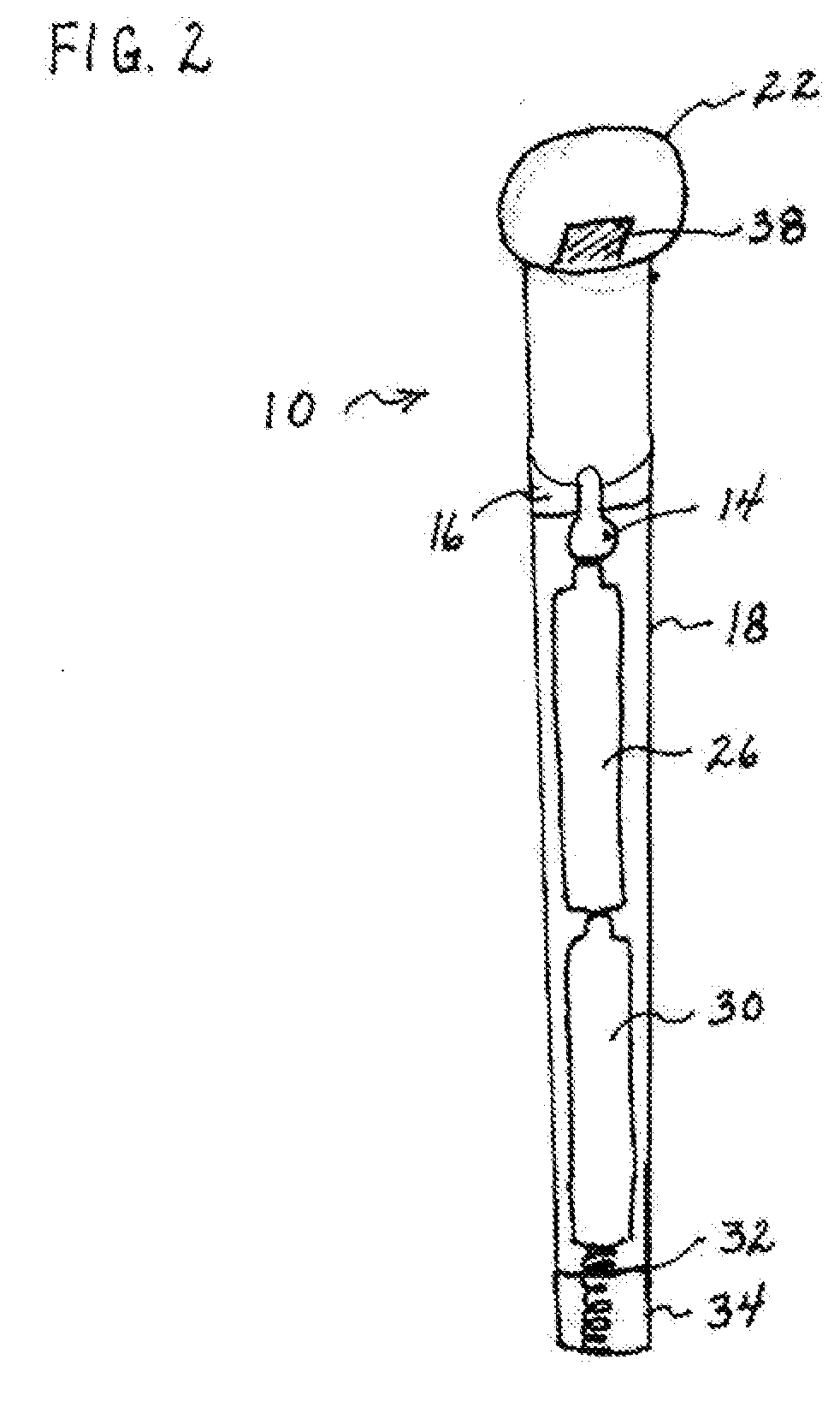
[0018] Referring to FIG. 1 and 2 collectively, an exemplary embodiment of a pocket otoscope 10 of the invention is shown. The pocket otoscope generally utilizes an intense, full spectrum, light emitting diode (LED) 14 that has at least an average bulb life of 100,000 hours of continuous use at low power to illuminate hidden areas and is useable by physicians and caregivers for examining ear canals and eardrums. In the exemplary embodiment, pocket otoscope 10 generally includes a tube-shaped frame 18 and head portion 22. The tube-shaped frame 18 may enclose a source of electrical power for the LED 14, which may be two removable 1.5 V AAA sized batteries 26, 30, which are insertable through rear end 32 of frame 18 and connected to power LED 14. The LED 14 is generally removably seated in a holder 16. The tube-shaped frame 18 may have a circular, s...


PUM


Abstract

The otoscope including an elongated body member having a water resistant substantially hollow interior, a head member attached to the distal end of the body member, a power source positioned in the water resistant substantially hollow interior of the body member, a light emitting diode positioned in the water resistant substantially hollow interior portion of the body member and being in selective electrical communication with the power source, and a light emitting diode holder positioned within the water resistant substantially hollow interior portion of the body member and having a concave surface facing the head member, the light emitting diode holder having an aperture formed through a central axis thereof, the aperture being sized to receive the distal end of the light emitting diode. There is a seal between the end of light emitting diode that extends through the aperture and the aperture itself thus exposing only the end of the LED light to the external environment. Since the Light emitting diode burns cool unlike incandescent light sources there is no harm to it from moisture even after it has been burning for extended periods. The otoscope head member also contains a light reflecting surface positioned in the path of light being emitted from the end of the light emitting diode that extends out the aperture, the reflecting member being positioned at an angle to direct the light at a 90 degree angle down the otoscope speculum and into the ear canal for use in visualization via the magnifying lens.

Description

BACKGROUND OF THE INVENTION [0001] 1. Field of the Invention [0002] Embodiments of the invention generally relate to an improved small light weight otoscope having a low current draw light emitting diode as a source of illumination incased in a water resistant housing. [0003] 2. Description of the Related Art [0004] Otoscopes are generally used by physicians, nurses, and health-givers to examine ear canals and ear drums. Conventional hand-held otoscopes with incandescent light sources have been developed to illuminate ear canals and magnifying lenses to magnify the illuminated area for examination. However, difficulties have been encountered with the useful lifetime of the light bulbs and batteries used in conventional devices, as the current draw of conventional bulbs generally runs the battery of a conventional otoscope dead in a matter of hours. Additionally, conventional bulbs used in conventional otoscopes have been shown to be easily damaged from both accidental dropping of th...

Claims


Application Information

Patent Timeline
IPC IPC(8): A61B1/06
CPCA61B1/00071A61B1/227A61B1/0684A61B1/0669A61B1/00096
Inventor SCHMITZ, JAMES DAVID
Owner SCHMITZ JAMES DAVID
Learn More