Tonsillith removing device

a technology of removing device and tonsil, which is applied in the field of personal cleaning devices, can solve the problems of ineffective methods, severe affecting patients' social activities and romantic relationships, and affecting the social activities of patients, and achieves the effect of easy removal

Inactive Publication Date: 2007-11-01
PAN HONGJUN
View PDF2 Cites 13 Cited by
  • Summary
  • Abstract
  • Description
  • Claims
  • Application Information

AI Technical Summary

Benefits of technology

[0005] It is therefore one objective of the present invention to provide a tonsill

Problems solved by technology

Such bad breath severely affects patients' social activities and romantic rela

Method used


Image

  • Tonsillith removing device
  • Tonsillith removing device
  • Tonsillith removing device

Examples


Embodiment Construction

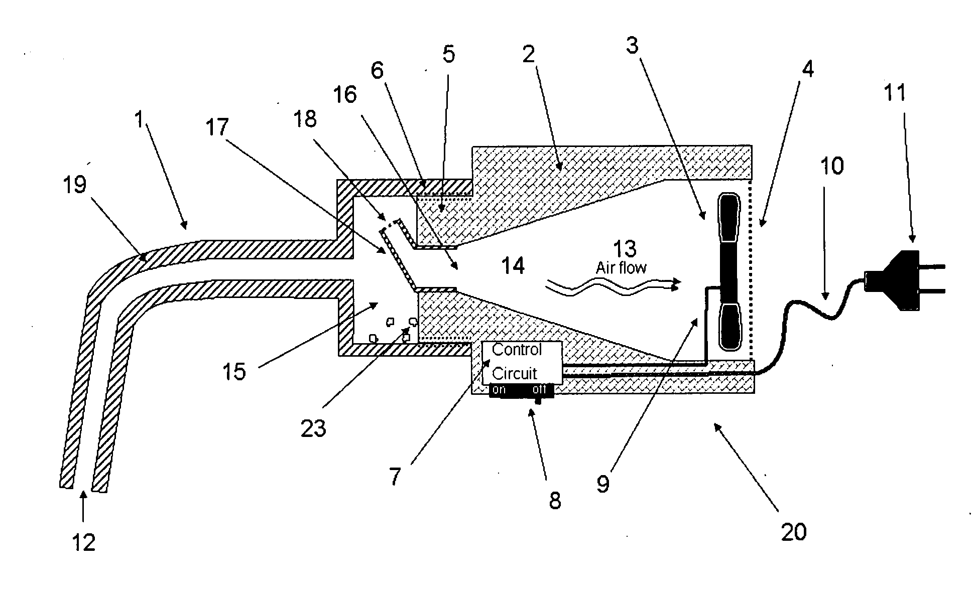
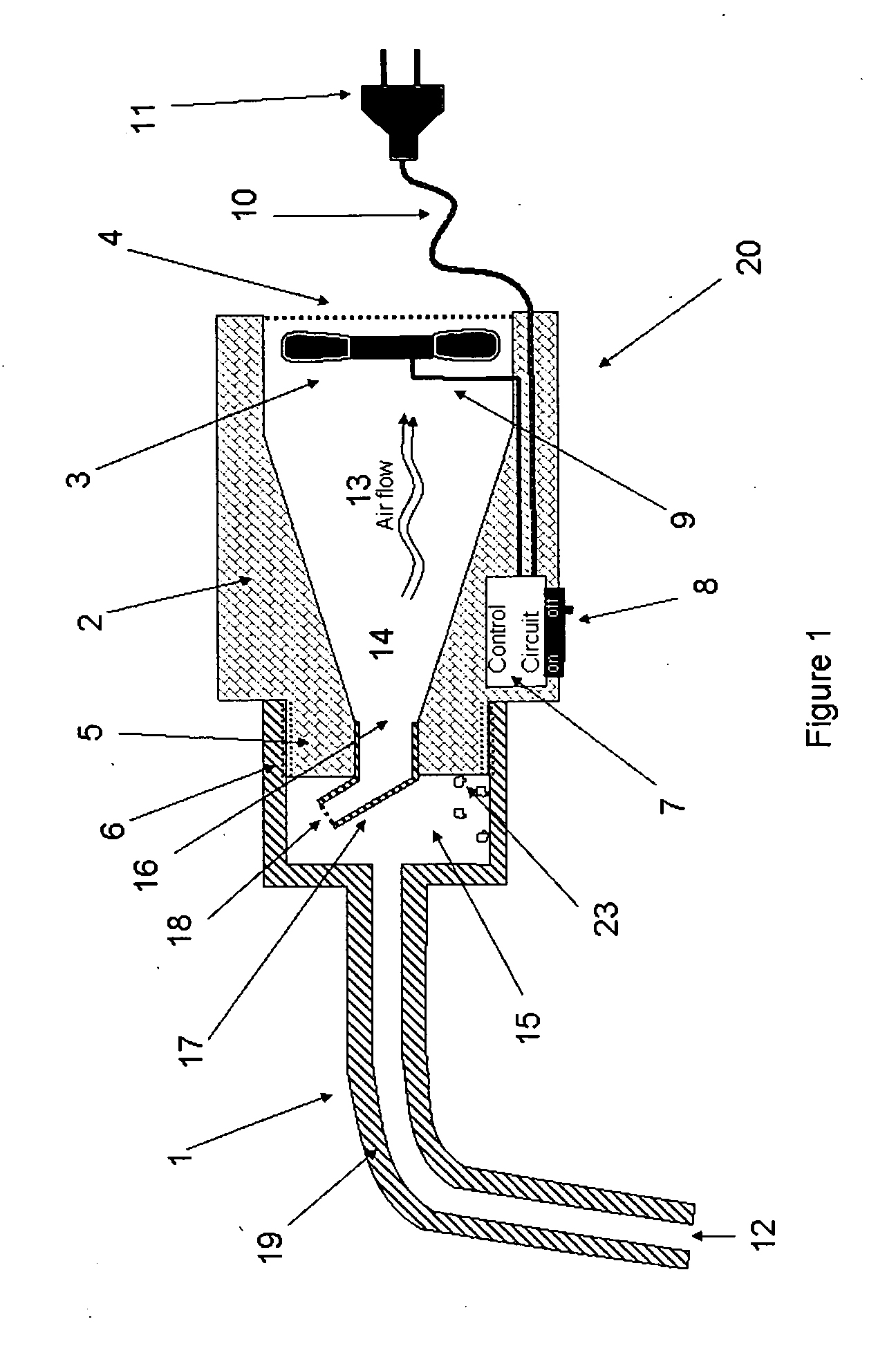
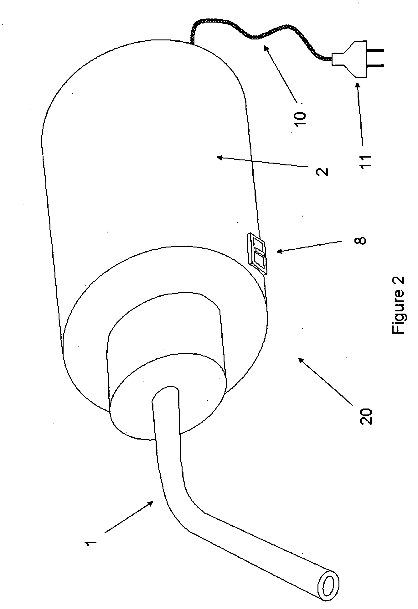
[0014] Referring in detail to the FIG. 1, the tonsillith removing device 20 comprises the suction channel element 1 and the suction mechanism unit 2. The suction channel element 1 has a round bottle cap shaped portion with threads 6 inside and a tube 19 is extended from the center of the round bottle cap shaped portion. One opening 12 of the tube has a smooth edge and surface that is placed on the tonsil crypts when it is in use. The tube can be angled or straight, however, the angled tube allows user to have a better view of the location of tonsillith in the back of the mouth during the operation. The suction mechanism unit 2 has a round cylinder shape, a short section 5 of the cylinder shape has smaller size with threads 6 on the out side surface. The suction mechanism unit 2 has two open ends with different sizes. A electric fan 3 is installed at the large open end. The size of inner chamber 14 gradually decreases towards to the smaller open end 16. An angled tube 17 is inserted ...


PUM


Abstract

A tonsillith removing device for use in removing tonsillith and other undesired matter from a user's tonsil crypts is described. The device comprises a suction channel element and a suction mechanism unit. The suction force is provided by an electric fan installed in the suction mechanism unit housing. The device has a retention feature for retaining the sucked tonsillith and undesired matter. The suction channel element can be easily detached from the suction mechanism unit and the retained tonsillith and undesired matter can be cleaned.

Description

BACKGROUND OF THE INVENTION [0001] 1. Field of the Invention [0002] The present invention relates to a device for personal cleaning and, more particularly, to a device for removing the undesired matter from user's tonsils and, even more particularly, the invention relates to a device for removing tonsillith (or called tonsil stone, tonsillolith, calculi of the tonsil) from the tonsil crypts (or called tonsil pockets). [0003] 2. Background Information [0004] About 85% of people suffer the halitosis (bad breath) which can be chronic or pathological disorder stemming from non-oral sources as well as oral sources. One of the main oral sources is the tonsillith formed in the tonsil crypts. There are more than 5% of people from young kids to elder adults having halitosis caused by tonsillith. The tonsillith is the accumulation of food particles, bacteria, leukocyte, dead white cells, and dried mucus. The accumulation products are colored white or yellow, have a rough texture similar to co...

Claims


Application Information

Patent Timeline
IPC IPC(8): A61B17/22
CPCA61B17/24A61B2217/005A61B2017/22079
Inventor PAN, HONGJUN
Owner PAN HONGJUN
Why Eureka
Try Eureka