Leg structure of office chair

a leg structure and office chair technology, applied in the field of leg structure of office chairs, can solve the problems of high material cost and some defects in conventional chairs, and achieve the effect of supporting the user's weigh

Inactive Publication Date: 2007-11-08
LAI SHU MU
View PDF3 Cites 7 Cited by
  • Summary
  • Abstract
  • Description
  • Claims
  • Application Information

AI Technical Summary

Benefits of technology

[0006]The primary object of the present invention is to provide a leg structure of an office chair that comprises a leg defined with a fitting portion for the connection with a support post, at the periphery of the fitting portion being radially arranged a plurality of leg racks, and beneath one end of each of the leg racks being provided with a sliding wheel, wherein an upright leg pillar is extendedly disposed at the lower end of the fitting portion, and another sliding wheel is mounted beneath the leg pillar for abutting against the ground such that the leg pillar and its sliding wheel can support the user's weight so as to reduce the loading weight of the leg racks of the chair, thus enabling to prolong the service lives of the leg racks.
[0007]The secondary object of the present invention is to provide a leg structure of an office chair that comprises an upright leg pillar extendedly disposed at the lower side of a fitting portion, and another sliding wheel mounted beneath the leg pillar for abutting against the ground, hence the loading weight of the leg racks of the chair can be reduced in such a manner that the leg can be made of cheaper plastic material, such as polypropylene so as to greatly diminish the material cost thereof.
[0008]Another object of the present invention is to provide a leg structure of an office chair, the lower side of the fitting portion of which is extendedly provided with the leg pillar in which a compression spring is mounted so as to absorb partial supported weight of the support post, thereby obtaining the stable support of the leg pillar and its sliding wheel.

Problems solved by technology

However, such a material is quite expensive, especially its current price rises quickly, accordingly this conventional chair still has some defects that could be improved.

Method used


Image

  • Leg structure of office chair
  • Leg structure of office chair
  • Leg structure of office chair

Examples


Embodiment Construction

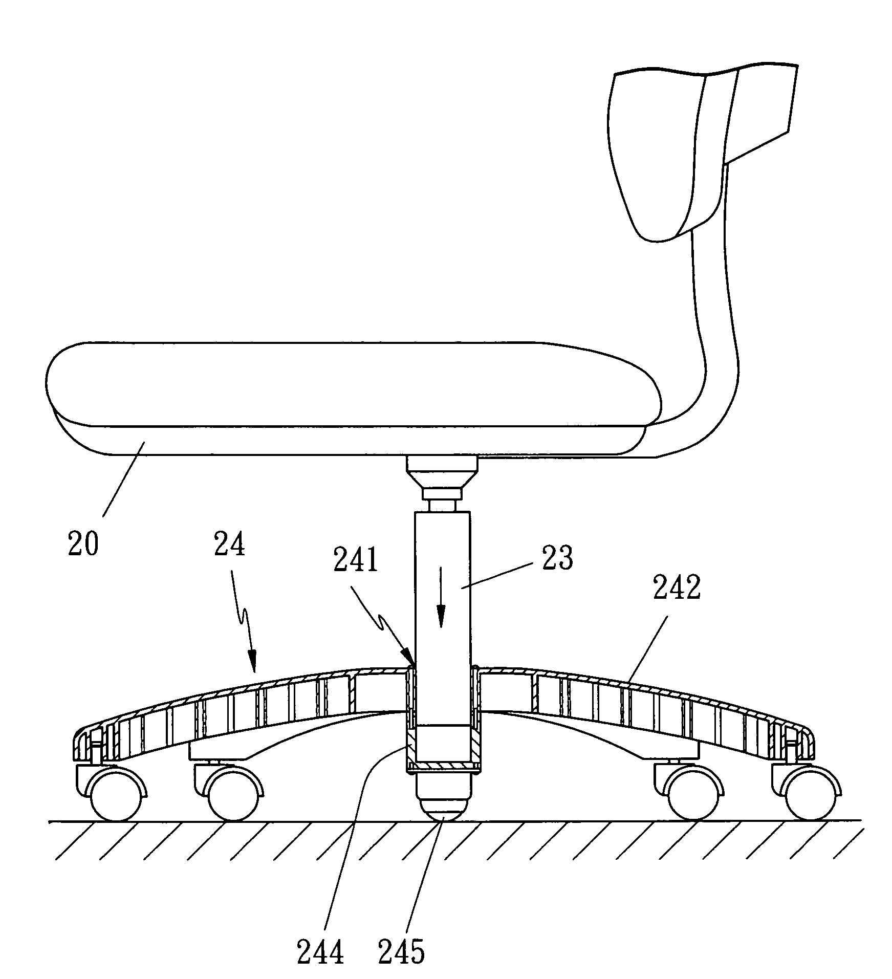
[0019]Referring to FIGS. 3-4, a leg structure of office chair in accordance with the present invention is shown and comprises a soft seat cushion 21 disposed at the upper side of a support plate 20, the side of which is couplingly defined with a backing pad 22 for the user's comfortness. Furthermore, a vertical support post 23 is couplingly mounted at the central position of the bottom of support plate 20, wherein the support post 23 is a rotatable adjusting screw or an air-compressed bar, accordingly the supported weight of support plate 20 will be passingly concentrated onto the support post 23 beneath which is couplingly defined with a leg 24 having a fitting portion 241, the periphery of which is radially arranged a plurality of leg racks 242, and a rotatable sliding wheel 243 is provided at the lower side of each of the leg racks 242, moreover, an upright leg pillar 244 is extendedly disposed at the lower end of the fitting portion 241 (the leg pillar 244 can also be integrally...


PUM


Abstract

A leg structure of an office chair comprises: a vertical support post coupled to the bottom of a support plate of an office chair, a leg coupled to the lower portion of support post, wherein the leg is defined with a fitting portion for the connection with the support post. At the periphery of fitting portion is outwardly arranged a plurality of leg racks in a radiation-shaped manner, and beneath the ends of leg racks are respectively provided with a sliding wheel, wherein an upright leg pillar is extendedly disposed at the lower end of the fitting portion, and a sliding wheel is mounted beneath the leg pillar for abutting against the floor, such that the leg pillar and the sliding wheel of leg pillar can support the weight of user so as to reduce the loading weights of leg racks of office chair, thus enabling to prolong the service lives of leg racks.

Description

BACKGROUND OF THE INVENTION[0001]1. Field of the Invention[0002]The present invention relates to a leg structure of an office chair which can support user's weight so as to reduce the loading weight of the leg racks of the chair, thus enabling to prolong the service lives of the leg racks.[0003]2. Description of the Prior Arts[0004]Referring to FIG. 1, a conventional chair comprises a soft seat cushion 11 disposed at the upper side of a support plate 10, the side of which is couplingly defined with a backing pad 12 for the user's comfortness. Furthermore, a vertical support post 13 is couplingly mounted at the central position of the bottom of the support plate 10, wherein the support post 13 is a rotatable adjusting screw or an air-compressed bar, accordingly, the supported weight of the support plate 10 will be passingly concentrated onto the support post 13 beneath which is couplingly defined with a leg 14 that is radially arranged a plurality of leg racks 141 so as to stably sup...

Claims


Application Information

Patent Timeline
Patent Type & Authority Applications(United States)
IPC IPC(8): F16M11/32
CPCA47C7/006
Inventor LAI, SHU-MU
Owner LAI SHU MU
Why Eureka
Try Eureka