Lightweight traction rod for urban rail vehicle

A technology of urban rail vehicles and traction rods, which is applied in the direction of traction devices, railway car body parts, transportation and packaging, etc. It can solve problems such as difficulty in achieving weight reduction goals, complex molding processes, and single product structure, and achieve reduction in vehicle operating capacity. The effect of reducing consumption, optimizing rod section, and reducing load weight

Inactive Publication Date: 2017-06-13
ZHUZHOU TIMES NEW MATERIALS TECH
View PDF13 Cites 3 Cited by
  • Summary
  • Abstract
  • Description
  • Claims
  • Application Information

AI Technical Summary

Problems solved by technology

[0006] At present, the lightweight method of urban rail vehicle traction rod is generally structural optimization method, or replace the original material with high-strength steel, the product weight reduction rate that can be achieved is less than 20%, and it is difficult to achieve the final weight reduction goal
For the polymer composite tie rods formed by the wrapping or molding process, the forming process is complicated, and the formed rod body structure is simple, which cannot meet the requirements of the urban rail vehicle traction rod structure
Due to the limitation of the forming process, the final formed product has a single structure, and the cross section of the rod is generally circular or rectangular

Method used


Image

  • Lightweight traction rod for urban rail vehicle
  • Lightweight traction rod for urban rail vehicle
  • Lightweight traction rod for urban rail vehicle

Examples


Embodiment Construction

[0029] The present invention will be further described in detail below with reference to the accompanying drawings and specific embodiments.

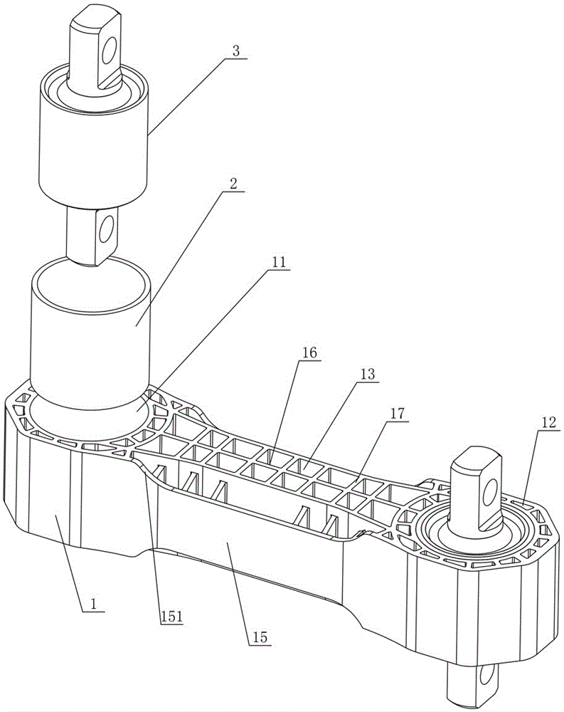
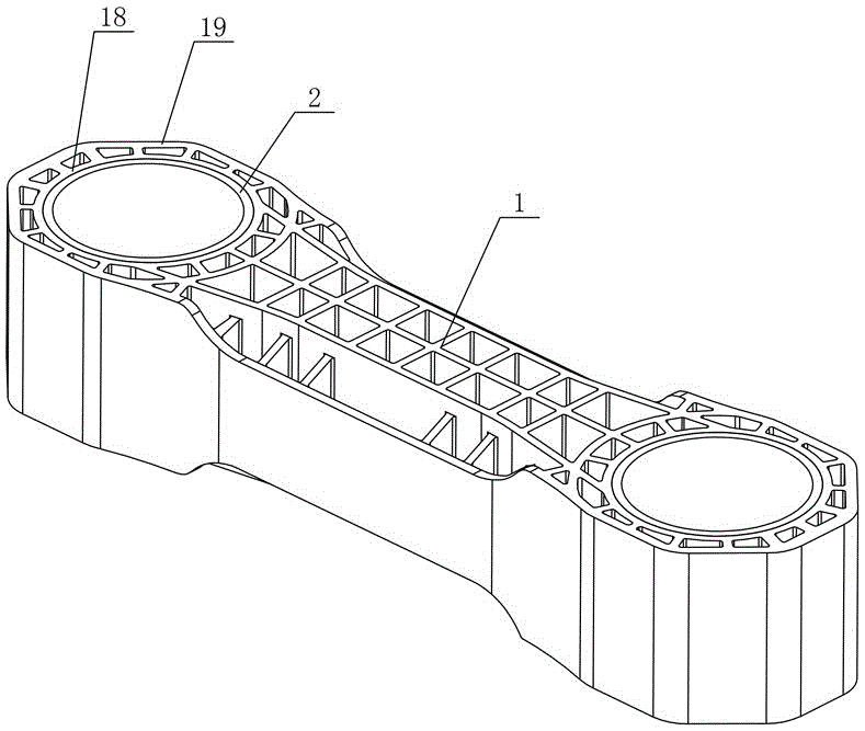
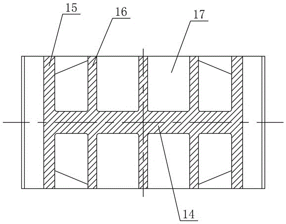
[0030] Figure 1 to Figure 4 The first embodiment of the lightweight traction rod for urban rail vehicles of the present invention is shown, including a rod body 1, two metal mounting rings 2 and two elastic nodes 3. The rod body 1 is formed of fiber-reinforced plastic, and the two elastic nodes are 3. It is made of high-strength steel. The two ends of the rod body 1 are provided with mounting holes 11. The two metal mounting rings 2 are integrally formed with the two mounting holes 11, respectively. The two elastic nodes 3 are respectively connected with the two metal mounting circles. The ring 2 has an interference fit. The rod body 1 is provided with a plurality of first hollow parts 12 along the periphery of the installation hole 11 that are consistent with the axis direction of the installation hole 11. The second hollow portion 1...


PUM


Abstract

The invention discloses a lightweight traction rod for an urban rail vehicle. The lightweight traction rod for the urban rail vehicle comprises a rod body, two metal mounting rings and two elastic joints. The rod body is formed by fiber reinforced plastic, and the two elastic joints are formed by steel and vulcanization. Mounting holes are formed in two ends of the rod body; the two metal mounting rings are matched with the two mounting holes correspondingly in an integral molding mode; the two elastic joints are in interference fit with the two metal mounting rings correspondingly; a plurality of first hollow portions which are consistent with the mounting holes in the axial direction are arranged at the rod body along the periphery of the mounting holes; and a plurality of second hollow portions consistent with the mounting holes in the axial direction are arranged at the part, between the two mounting holes, of the rod body. The traction rod has the advantages of being high in strength, capable of being produced in batches, and capable of reducing the weight of the vehicle performance load and vehicle operating energy consumption.

Description

technical field [0001] The invention mainly relates to the engineering field of urban rail vehicles, in particular to a lightweight traction rod for urban rail vehicles. Background technique [0002] The traction rod assembly applied to the urban rail vehicle, its main structure is the elastic node of the traction rod body and the metal rubber compound, the traction rod assembly connects the car body and the bogie through the elastic node, and mainly plays the role of connecting and transmitting traction during the operation of the vehicle. Brake load, and achieve vibration reduction and noise reduction through elastic nodes. [0003] The current traction rod has installation holes for installing elastic nodes at both ends of the rod body. The cross section of the rod body generally adopts three types of structures: round, rectangular and I-shaped. Because the rod body is mainly made of high-strength steel material, the quality is large and the overall appearance is large. ...

Claims


Application Information

Patent Timeline
Patent Type & Authority Applications(China)
IPC IPC(8): B61G9/20
CPCB61G9/20
Inventor 周炜黄友剑林胜荣继刚葛琪
Owner ZHUZHOU TIMES NEW MATERIALS TECH
Why Eureka
Try Eureka