Centrifuge and swing rotor for centrifuge

a centrifuge and swing rotor technology, applied in the direction of centrifuges, etc., can solve the problems of increasing centrifugal acceleration, large structure, and high cost of titanium materials, so as to prolong the life of the rotor, reduce the load weight, and reduce the bending moment.

Active Publication Date: 2017-02-23
EPPENDORF HIMAC TECH CO LTD
View PDF5 Cites 3 Cited by
  • Summary
  • Abstract
  • Description
  • Claims
  • Application Information

AI Technical Summary

Benefits of technology

[0011]According to the invention, the load weight applied on the rotating shaft and the bending moment can be significantly reduced to half or less of those of the conventional technology, and the rotating shaft can be used without breakage or deformation even if the rotating shaft is made to be light in weight and repeatedly receives bending stress in each centrifugation operation. Since the load weight on the rotor can be reduced, the effect of prolonging the lifespan of the rotor and the rotating shaft to reduce the costs is achieved.

Problems solved by technology

In terms of the form that swings the bucket to the horizontal by the rotating shaft disposed on the rotor or the bucket and from there bends the rotating shaft to seat the bucket on the rotor, so as to hold the load caused by the centrifugal force of the bucket with the rotor body, as disclosed in Patent Literature 1, conventionally it is inevitable to increase the section modulus to ensure the strength of the rotating shaft itself such that the rotating shaft is not broken under the centrifugal force caused by its own weight or the load of the bucket, but it results in the problem of a larger structure.
Moreover, for the convenience of ensuring the strength, an aluminum alloy that is inexpensive and has a small specific gravity may be used, but usually it does not suffice as the rotating shaft that is to be used in the swing rotor for generating centrifugal acceleration of 100,000×g or more.
The conventional idea is to prevent breakage by enhancing the rigidity of the rotating shaft, but there is a limit as the centrifugal acceleration increases.
Nevertheless, using titanium as the material is costly.
In addition, titanium is difficult to cut as compared to the aluminum alloy or stainless steel, which will increase the production costs and inevitably raise the sales price for the customers and impose a cost burden on the purchasers.
As a result, the load weight on the rotor increases.

Method used


Image

  • Centrifuge and swing rotor for centrifuge
  • Centrifuge and swing rotor for centrifuge
  • Centrifuge and swing rotor for centrifuge

Examples


first embodiment

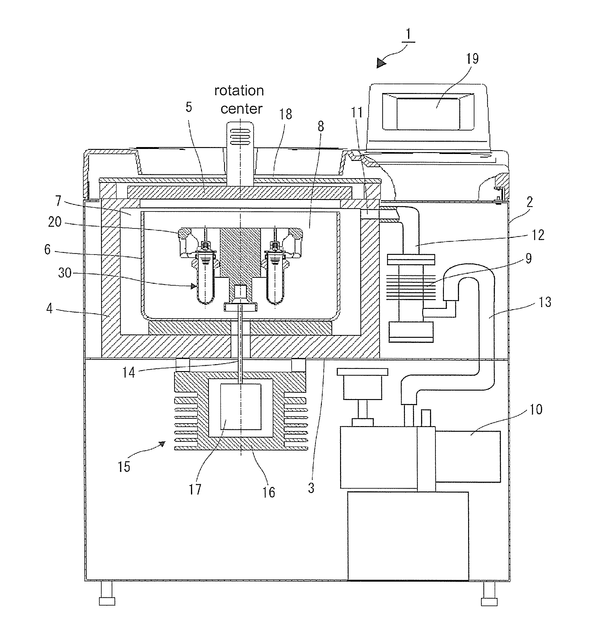
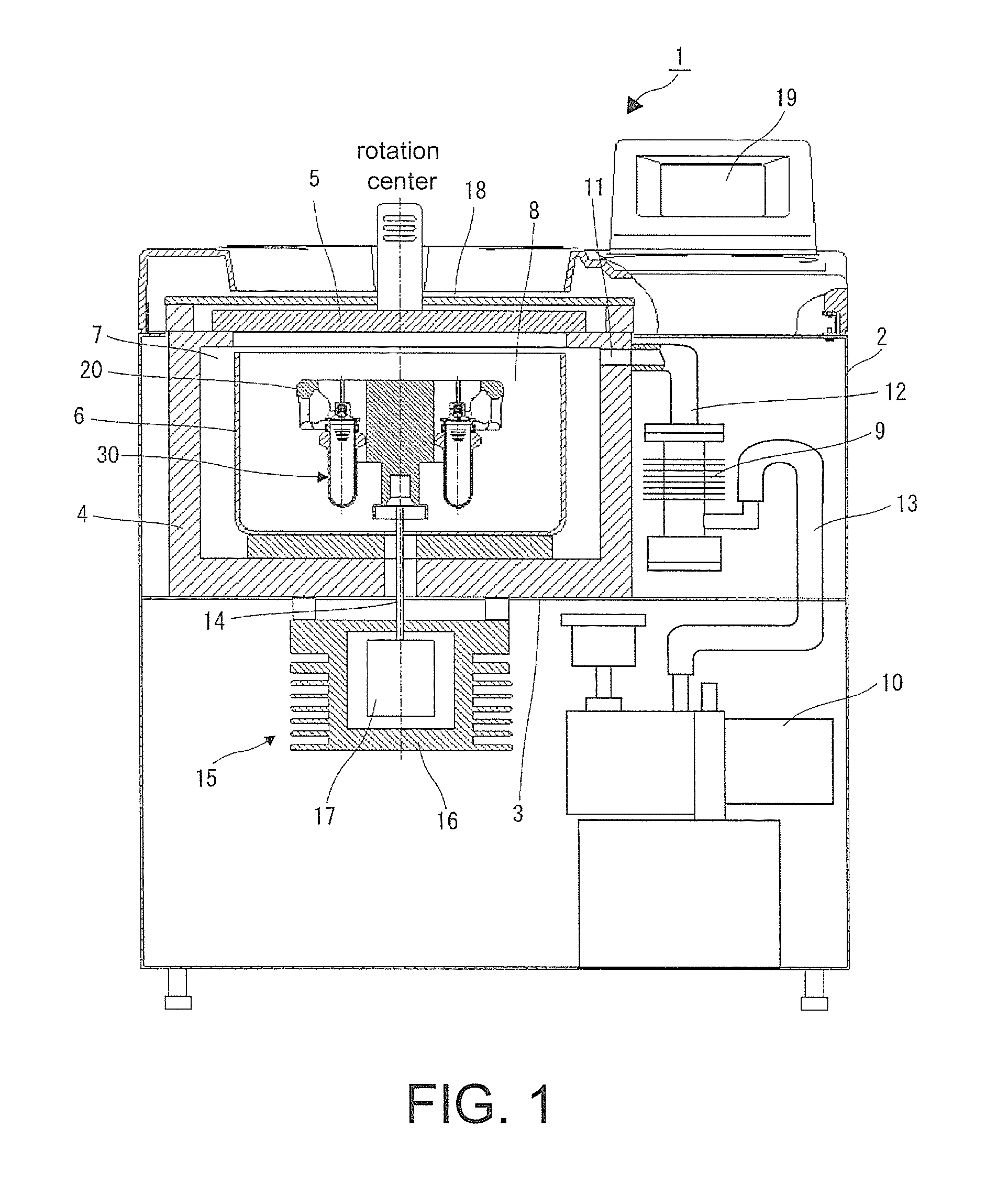
[0028]Referring to FIG. 1, a centrifuge 1 of the first embodiment is housed in a box-shaped case 2 that is made of sheet metal or plastic, and the interior of the case 2 is partitioned into an upper space and a lower space by a horizontal partition plate 3. A protective wall 4 is disposed in the upper space. The protective wall 4 and a door 5 define a decompression chamber 7 where a bowl 6 is housed. Then, by closing the door 5, the decompression chamber 7 is sealed by a door packing (not shown). The bowl 6 has a cylindrical shape that is open on the upper side. A rotor 20, on which a sample container 30 is disposed in a swingable manner, is housed in an interior space (rotor chamber 8) of the bowl 6.

[0029]An oil diffusion vacuum pump 9 and an oil rotation vacuum pump 10 are connected in series to serve as a vacuum pump for discharging the atmosphere in the decompression chamber 7 to create a vacuum (decompression). That is, a vacuum drawing opening 11 formed on the protective wall ...

second embodiment

[0056]In the second embodiment, referring to FIGS. 13(a)˜13(c), two rotating shafts 40′ are connected via a hollow part 32′ of a lid part 31. FIG. 13(a) is a perspective view showing the configuration of the rotating shafts 40′, FIG. 13(b) is a partial cross-sectional perspective view showing the configuration of the lid part 31′ including the rotating shafts 40′, and FIG. 13(c) is a longitudinal cross-sectional view showing the configuration of the lid part 31′ including the rotating shafts 40′.

[0057]As shown in FIG. 13(a), a connection part 43′ of the rotating shaft 40′ does not have the rotating shaft sliding surface 45 that the rotating shaft 40 has in the first embodiment, but has the pin sliding hole 45 and the contact surface 46. As shown in FIG. 13(b), two press-fit holes 36 (one of the press-fit holes 36 is not shown) are formed side by side in the horizontal direction on the peripheral surface of the hollow part 32′ of the lid part 31′. As shown in FIG. 13(b) and FIG. 13(c...

third embodiment

[0059]In the third embodiment, referring to FIGS. 14(a)˜14(b), two rotating shafts 40″ are connected via an intermediate member 47. FIG. 14(a) is a perspective view showing the configuration of the rotating shafts 40″ and FIG. 14(b) is a partial cross-sectional perspective view showing the configuration of a lid part 31″ including the rotating shafts 40″.

[0060]As shown in FIG. 14(a), the connection parts 43″ of the two rotating shafts 40″ are respectively connected to the intermediate member 47 by a pin 48. The pins 48 respectively connecting the two rotating shafts 40″ to the intermediate member 47 are set in parallel. Then, as shown in FIG. 14(b), the two rotating shafts 40″ connected via the intermediate member 47 are disposed such that the mutual connection parts 43″ and the intermediate member 47 are located in the hollow part 32″ of the lid part 31″, and like the first embodiment, the spacer 70 and the disc springs 71 are interposed between the contact surfaces 46 of the conne...


PUM


Abstract

The present invention provides a centrifuge comprising a lid section of a sample container, the lid section having a rotating shaft for swinging, and a swing-type rotor, and the centrifuge conducts centrifugation operation in a state where the sample container is seated in a bucket housing section by making the sample container in which the rotating shaft is mounted to a rotating shaft engagement groove of the rotor swing due to the rotation of the rotor. The rotating shaft comprises a plurality of members connected by a connection section and is configured so as to be bendable at the connection section by a centrifugal load accompanying the rotation of the rotor.

Description

BACKGROUND OF THE INVENTION[0001]1. Field of the Invention[0002]The invention relates to a centrifuge for separating a sample in the fields of medicine, pharmacy, genetic engineering, biotechnology, and so on, and particularly relates to improvement of a rotating shaft structure for use in a centrifuge with a swing type rotor and a sample container for the centrifuge.[0003]2. Description of Related Art[0004]A centrifuge is a device, which includes a rotor capable of housing a plurality of sample containers filled with samples therein and a driving means, such as a motor, rotationally driving the rotor in a rotor chamber, and rotates the rotor at a high speed to apply a centrifugal force, so as to centrifugally separate the samples in the sample containers. Centrifuge rotors can be roughly divided into two types, i.e. angle rotor and swing rotor. In the case of the angle rotor, a plurality of sample containers filled with samples therein are housed in housing holes, and a lid is fast...

Claims


Application Information

Patent Timeline
Patent Type & Authority Applications(United States)
IPC IPC(8): B04B9/00B04B5/02
CPCB04B5/02B04B9/00B04B5/0421
Inventor SATO, JUNNEMOTO, KENICHI
Owner EPPENDORF HIMAC TECH CO LTD
Why Eureka
Try Eureka