Target positioning method and system

A target positioning and target point technology, applied in the field of target positioning methods and systems, can solve the problems of large positioning limitations, increase the load weight of the aircraft, and not use position information, so as to reduce the load weight and cost, and increase the range of target positioning Effect

Pending Publication Date: 2021-06-18
BEIJING JINGBANGDA TRADE CO LTD +1
View PDF0 Cites 2 Cited by
  • Summary
  • Abstract
  • Description
  • Claims
  • Application Information

AI Technical Summary

Problems solved by technology

[0006] Active target positioning technology relies on laser ranging, which is fast and accurate. However, the flying height unit of fixed-wing or other manned or unmanned aerial vehicles equipped with aerial photoelectric imaging systems is at the kilometer level, requiring high-power, high-speed Quality laser rangefinder machines, which increase the payload weight of the aircraft and also increase the cost of targeting
At the same time, the proportional positioning method used in the passive target positioning technology can only solve the position of the center of the image, and does not use the position information of the target point in the image, so the positioning limitation is large

Method used


Image

  • Target positioning method and system
  • Target positioning method and system
  • Target positioning method and system

Examples


Embodiment Construction

[0056] The present invention is described below based on examples, but the present invention is not limited to these examples. In the following detailed description of the invention, some specific details are set forth in detail. The present invention can be fully understood by those skilled in the art without the description of these detailed parts. In order to avoid obscuring the essence of the present invention, well-known methods, procedures, and flow charts are not described in detail. Additionally, the drawings are not necessarily drawn to scale.

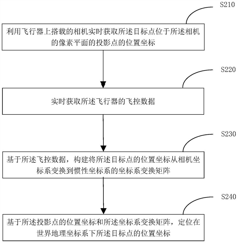
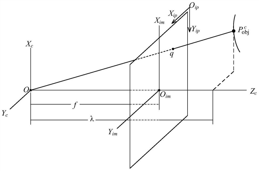
[0057] figure 2 is a schematic flowchart of a target positioning method according to an embodiment of the present invention. image 3 A schematic diagram showing a pinhole camera model of an object localization method according to an embodiment of the present invention. Such as image 3 As shown, the camera coordinate system {X c ,Y c ,Z c}, the origin O in the camera coordinate system c Located at the optical center...


PUM


Abstract

The invention discloses a target positioning method and system, and relates to the technical field of target positioning. The method comprises the following steps: acquiring position coordinates of a projection point of a target point on a pixel plane of a camera in real time by using a camera carried on an aircraft; acquiring flight control data of the aircraft in real time; based on the flight control data, constructing a coordinate system transformation matrix for transforming the position coordinate of the target point from a camera coordinate system to an inertial coordinate system; and positioning the position coordinate of the target point in a world geographic coordinate system based on the position coordinate of the projection point and the coordinate system transformation matrix. According to the target positioning method of the embodiment of the invention, a laser ranging machine is prevented from being carried on the aircraft, the load weight and the cost of the aircraft are reduced, and the target positioning range of the target positioning method of the aircraft is improved.

Description

technical field [0001] The present invention relates to the technical field of target positioning, in particular to a target positioning method and system. Background technique [0002] At present, aerial photoelectric imaging systems are commonly used to detect and track ground targets. Aerial optoelectronic imaging systems are used on fixed-wing or other manned or unmanned aerial vehicles operating at high altitudes. To achieve ground target positioning, it is necessary to obtain the position and attitude of the photoelectric imaging system relative to the aircraft in real time, as well as the distance of the photoelectric imaging system relative to the ground target. The GPS information and inertial navigation data on the airborne side of the aircraft are transformed through the coordinate system to complete the target positioning. In the whole target positioning process, obtaining the distance value between the aircraft and the target is the key. [0003] In the prior...

Claims


Application Information

Patent Timeline
Patent Type & Authority Applications(China)
IPC IPC(8): G01C21/20G01C11/04G01C21/16G06T7/73
CPCG01C11/04G01C21/165G01C21/20G06T2207/30181G06T7/73
Inventor 陈宇楠
Owner BEIJING JINGBANGDA TRADE CO LTD
Why Eureka
Try Eureka