Regeneration Device for Rotary Traveling Wave Oscillator

a technology of rotary traveling wave and oscillator, which is applied in the direction of oscillator generator, pulse generation by logic circuit, pulse technique, etc., can solve the problems of compounded dc instability, low power dissipation and drive requirements, etc., and achieves faster p-type device, low noise characteristics, and higher frequency operation

Inactive Publication Date: 2007-11-08
ANALOG DEVICES INC
View PDF13 Cites 3 Cited by
  • Summary
  • Abstract
  • Description
  • Claims
  • Application Information

AI Technical Summary

Benefits of technology

[0016] One advantage of the present invention is that the oscillator has low noise characteristics.
[0017] Another advantage is that slower type P-type devices are eliminated, thereby allowing higher frequency operation.

Problems solved by technology

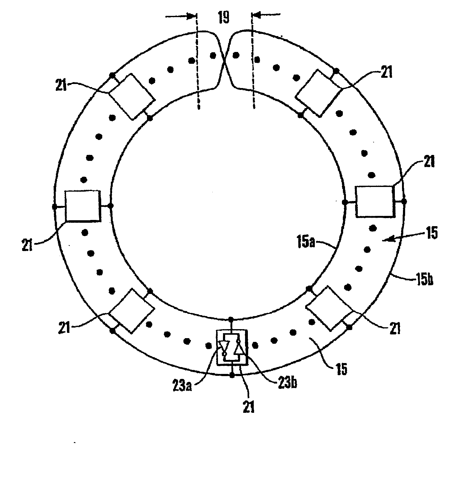
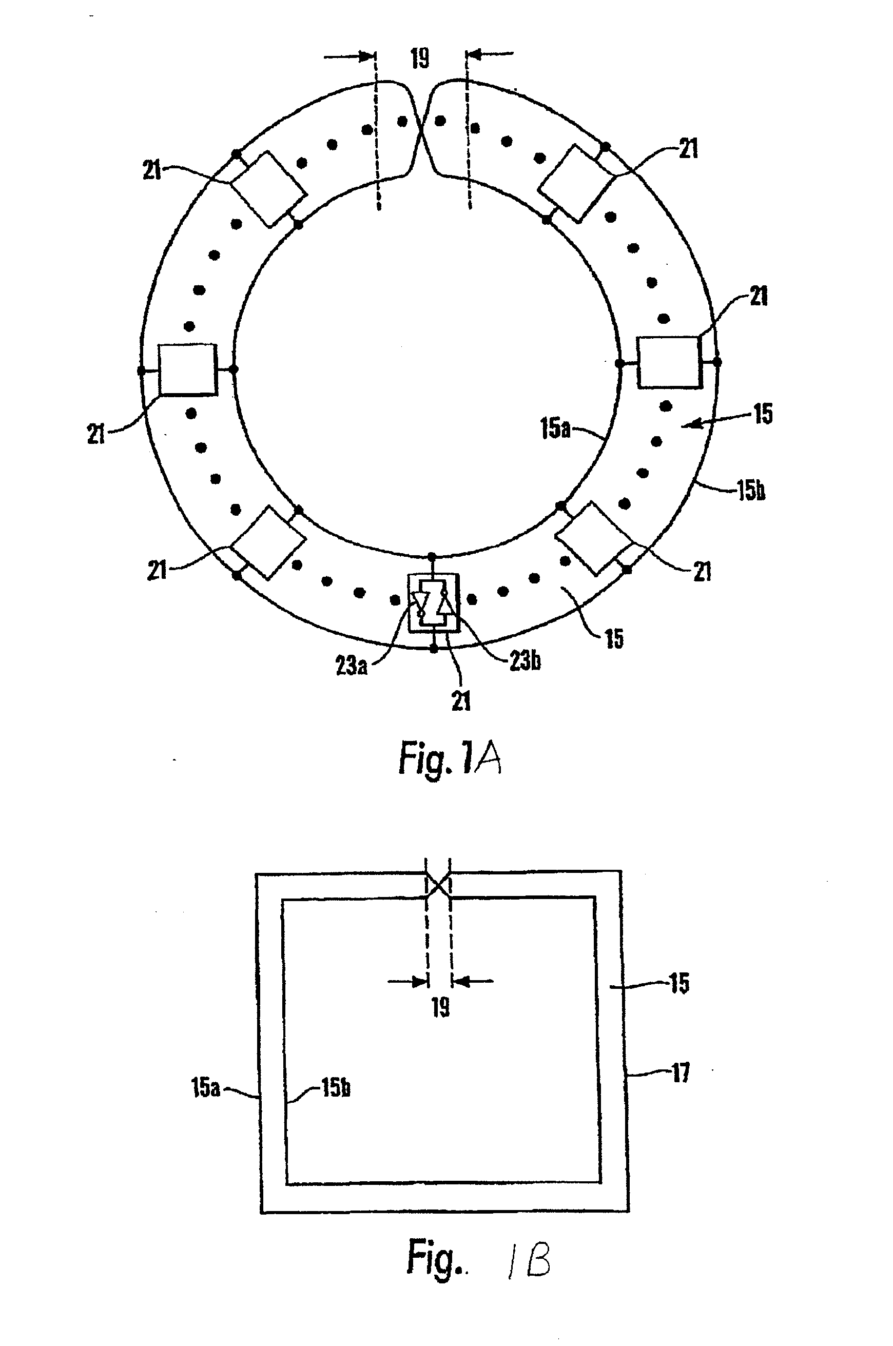
At the fundamental oscillating frequency F, the terminals of the amplifiers 21 appear substantially unloaded, due to the transmission-line 15 being ‘closed-loop’ without any form of termination, which results very desirably in low power dissipation and low drive requirements.
The evident continuous DC path directly connecting all inputs and outputs of the inverters has no stable DC operating point, and this DC instability is compounded by the regenerative (+Ve feedback) action of the back-to-back inverters.

Method used


Image

  • Regeneration Device for Rotary Traveling Wave Oscillator
  • Regeneration Device for Rotary Traveling Wave Oscillator
  • Regeneration Device for Rotary Traveling Wave Oscillator

Examples


Embodiment Construction

[0028]FIG. 5A shows an alternative to the regeneration devices described above. Instead of the regeneration devices, a plurality of current switching devices 60a-g and a conductive element 62 with high-impedance are employed. The conductive element 62 is connected to a first supply voltage 64 (such as Vdd) to provide current to the oscillator at any point along the conductors 66a,b that make up the oscillator 68. Typically, the conductive element 62 has an impedance that is about twice the impedance of the transmission lines of the oscillator. Each of the current switching devices 60a-g is connected between the conductors, for example conductors 66a,b, of the two-conductor transmission line 72a,c and a second reference voltage (such as ground, shown in FIG. 6A). Thus, the conductive element 62 supplies current to the conductors 66a,b and the current switches 60a-g remove current from the conductors 66a,b, depending on the state of the conductors, where the state indicates which cond...


PUM


Abstract

An oscillator is described. The oscillator includes segments of two-conductor transmission line being connected together by an odd number of connection means to form a closed loop. A plurality of current switches is connected to the conductors of the segments and a high impedance element, such as an inductor or transmission line, is connected to a conductor of at least one segment. The high impedance element sources current into the closed loop and the current switches sink current from one or the other of the conductors of the loop depending on the state of the switch. The switches cause a wave to be established and maintained on the loop and the wave changes the state of the switches as it oscillates. One embodiment of the switches employs npn transistors whose emitters are connected to a current source and another uses NMOS transistors.

Description

CROSS-REFERENCE To RELATED APPLICATIONS [0001] This application claims priority to U.S. Provisional Patent Application Ser. No. 60 / 707,631, filed Aug. 11, 2005, entitled “REGENERATION DEVICE FOR ROTARY TRAVELING WAVE OSCILLATOR,” which is a continuation-in-part of pending U.S. application, Ser. No. 10 / 275,461, filed Apr. 7, 2003, and titled “ELECTRONIC PULSE GENERATOR AND OSCILLATOR”, which application is incorporated by reference into the present application. [0002] This application claims the benefit of application Ser. No. 10 / 275,461, which is a national stage application of PCT application, PCT / GB01 / 02069, publication number WO 01 / 89088, filed May 11, 2001, and this application and the PCT / GB01 / 02069 application claim priority to GB0011243.3, filed May 11, 2000, GB0024522.2, filed Oct. 6, 2000, and GB0102700.2, filed Feb. 3, 2001. The PCT / GB01 / 02069, GB0011243.3, GB0024522.2, and GB0102700.2 are incorporated by reference into the present application. U.S. Pat. No. 6,556,089 is i...

Claims


Application Information

Patent Timeline
Patent Type & Authority Applications(United States)
IPC IPC(8): H03B5/18
CPCH03B5/18H03B5/26H03B5/1847
Inventor BECCUE, STEPHEN MARK
Owner ANALOG DEVICES INC
Why Eureka
Try Eureka