Magnetic recording media and magnetic disk apparatus

a magnetic disk and recording media technology, applied in the field of magnetic disk apparatuses and recording media, can solve the problems that the head and the media interface is becoming difficult to prevent the head from contact, and achieve the effects of reducing the possibility of a crash of the magnetic head to said projection, high recording density, and small energy at a crash

Inactive Publication Date: 2005-02-08
HITACHI LTD
View PDF12 Cites 9 Cited by
  • Summary
  • Abstract
  • Description
  • Claims
  • Application Information

AI Technical Summary

Benefits of technology

As said magneto-resistive effect head, it is preferred to form the magneto-resistive sensor between two shield layers of soft magnetic material displaced to each other layer by from not less than 0.06 micron to not more than 0.18 micron. The output cannot be obtained enough in the high recording density area beyond 500 kFCI if the distance of the shield layers is greater than 0.18 micron. And it becomes not easy to keep enough insulation between the shield layer and the magneto-resistive sensor if the distance of the shield layers is less than 0.06 micron. It is preferred that the product (Br×t), where t is the thickness of said magnetic recording media, and remanent magnetization flux density Br, where Br is measured applying magnetic field along to the relative moving direction of the magnetic head against the magnetic recording media, is not less than 3.2 mA (40 Gauss·micron) and not more than 6.4 mA (80 Gauss·micron). It increases the danger to reproduce wrong information by degradation of reproducing output being left long time after being recorded if Br×t is less than 3.2 mA (40 Gauss·micron). It becomes ...

Problems solved by technology

However, the spacing is getting narrower rapidly in these days to achieve higher recording density, so that the head and me...

Method used


Image

  • Magnetic recording media and magnetic disk apparatus
  • Magnetic recording media and magnetic disk apparatus
  • Magnetic recording media and magnetic disk apparatus

Examples


embodiment 1

[Embodiment 1]

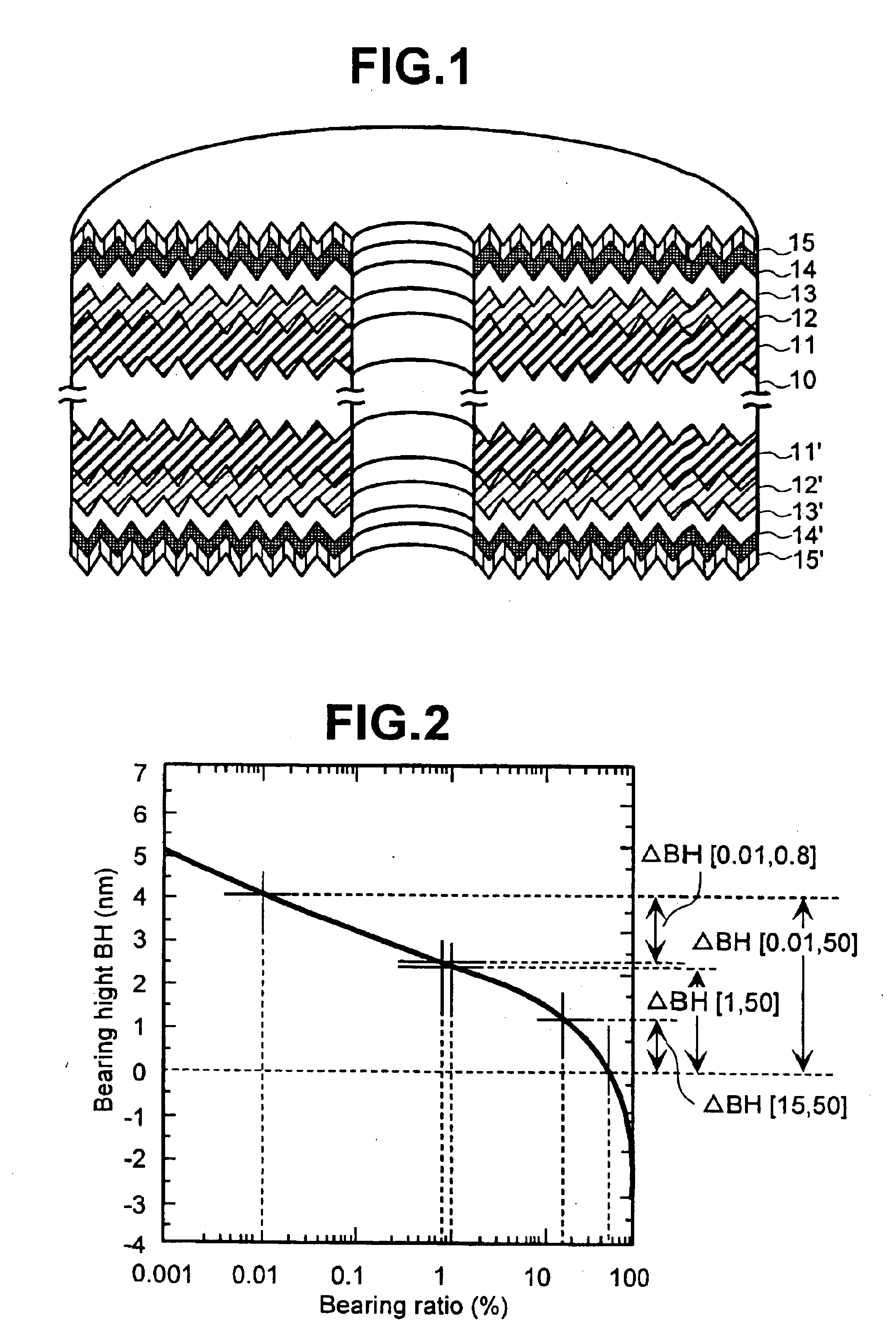
FIG. 1 is a drawing to illustrate a cross section of an embodiment of magnetic recording media of the present invention. A disk substrate of 0.635 thick and 2.5 inches type of Almino-silicate glass with the surface chemically tempered was used as a substrate 10. It was formed with multi-layer films, as follows, on the surface by using a static magnetron sputtering system (MDP250B) made by Intevac after cleaned up. First, the first under layers 11 and 11′ of 40 nm thickness composed of alloy with 65 at. % of Ni, 20 at. % of Cr and 15 at. % of Zr were formed on both sides of the surface of a substrate 10. Thereafter, it was heated up to about 230 deg. C. on the substrate using a lamp heater, and exposed in an environment of mixed gas of 5 mTorr pressure with 99% of Ar and 1% of O2 during 3.5 seconds. Then the second layers 12 and 12′ of 30 nm thickness composed of alloy with 80 at. % of Cr and 20 at. % of Ti were formed, magnetic layers 13 and 13′ of 20 nm thickness comp...

comparing example 1

[Comparing Example 1]

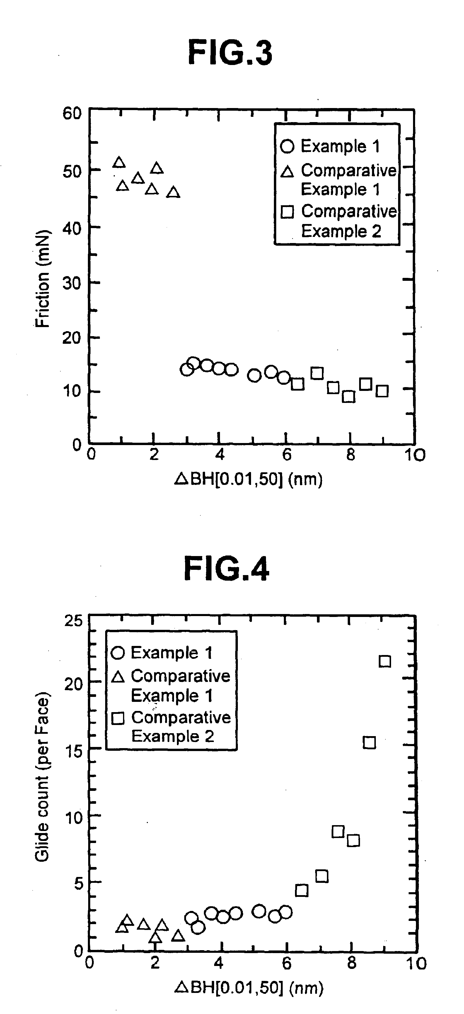
In this comparing example 1, the magnetic recording media was made under the same condition as the embodiment 1 described above except that Δ BH[0.01, 50] of media surface was from 1 nm to 2.6 nm.

The relation between the friction force and Δ BH[0.01, 50] of the media of present comparing example is plotted in FIG. 3. The friction force of the media in the present comparing example is from 46 mN to 52 mN, while the friction force was from 12 mN to 15 mN in case of the media in the embodiment 1. This means not only degradation of reliability but also impossibility of stable recording / reproducing. Therefore, it is difficult to achieve so high recording density as 11 gigabits per square inch or more in case of the present comparing example.

comparing example 2

[Comparing Example 2]

In this comparing example 2, the magnetic recording media was made under the same condition as the embodiment 1 described above except that Δ BH[0.01, 50] of media surface was from 6.3 nm to 9.1 nm.

As shown in FIG. 3, the friction force in comparing example 2 is from 8 mN to 13 mN, which is equivalent to the embodiment 1 or less. Therefore, there is little problem happened of wear reliability and stable recording / reproducing characteristics. However, as shown by FIG. 4, glide count is increased rapidly in accordance with Δ BH[0.01, 50] being larger. This means that the possibility of head crash is high and there is problem of wear reliability. Therefore, it is difficult to achieve so high recording density as 11 gigabits per square inch or more in case of the present comparing example.


PUM


Abstract

A magnetic recording media formed of magnetic alloy layer of Co as the main component on a substrate through an under-layer, a protective layer and a lubricant layer, stacked in this order, said under-layer comprises plural under-layers including a first under layer of a substantially amorphous and a second under layer of crystalline stacked in this order; and a Δ BH[0.01, 50] defined by |BH[0.01%]−BH[50%]|, as the difference between a height BH[0.01%] where a Bearing ratio is 0.01% and a height BH[50%] where a Bearing ratio is 50%, is not less than 3 nm and not more than 6 nm, where a Bearing Curve is given by a surface roughness curve of magnetic recording media.

Description

BACKGROUND OF THE INVENTIONThe present invention is related to a magnetic recording media which is possible to record large volume information and to a magnetic disk apparatus using this media, particularly suitable to a magnetic recording media and a magnetic disk apparatus for high density magnetic recording.The requirement for larger capacity to a magnetic disk apparatus is increasing more and more. There are some countermeasures in order to increase the recording density such as (1) improvement of the sensitivity of a reproducing part of a magnetic head, (2) narrower distance between a head element and a recording surface of a magnetic recording media and (3) higher efficiency of a signal processing.The adoption of a composite magnetic head, which is separated into a recording part and a reproducing part and uses a highly sensitive element utilizing magneto-resistive effect as the reproducing part, is rapidly increased in these years. Recently, a magnetic head utilizing the effe...

Claims


Application Information

Patent Timeline
IPC IPC(8): G11B5/73G11B5/64G11B5/62
CPCG11B5/64G11B5/7325Y10T428/265Y10S428/90G11B5/737
Inventor SHODA, MITSUHIROENDO, NAOTOGODA, NORIYOSHIHOSOE, YUZURUKATO, AKIRA
Owner HITACHI LTD
Why Eureka
Try Eureka