Multistage switch

Inactive Publication Date: 2007-11-08
MURATA MFG CO LTD
View PDF9 Cites 2 Cited by
  • Summary
  • Abstract
  • Description
  • Claims
  • Application Information

AI Technical Summary

Benefits of technology

[0017] When semiconductor magnetoresistive elements are used as the two magnetoelectric transducers, the semiconductor magnetoresistive element defining as the first magnetoelectric transducer preferably includes a predetermined number of short-circuiting electrodes to achieve a predetermined magnetoresistive effect, and the second semiconductor magnetoresistive element preferably includes no short-circuiting electrodes or a smaller number of short-circuiting electrodes to substantially eliminate the magnetoresistive effect. With such a simple structure, the magnetoresistive effect of the second magnetoelectric transducer can be substantially eliminated, and the temperature characteristics of the two magnetoelectric transducers can be identical.
[0018] Furthermore, an operating mechanism of the switch push button and an

Problems solved by technology

Thus, the user who wishes to obtain a desired operating state may not successfully obtain the desired operating state due to the mismatch between the user's feeling of operation and the actual operation of the multistage switch.
If the user fails to accurately press the switch push button, the shutter may oft

Method used


Image

  • Multistage switch
  • Multistage switch
  • Multistage switch

Examples


Example

[0026] The features of the present invention will be described in more detail hereinafter with respect to preferred embodiments of the present invention.

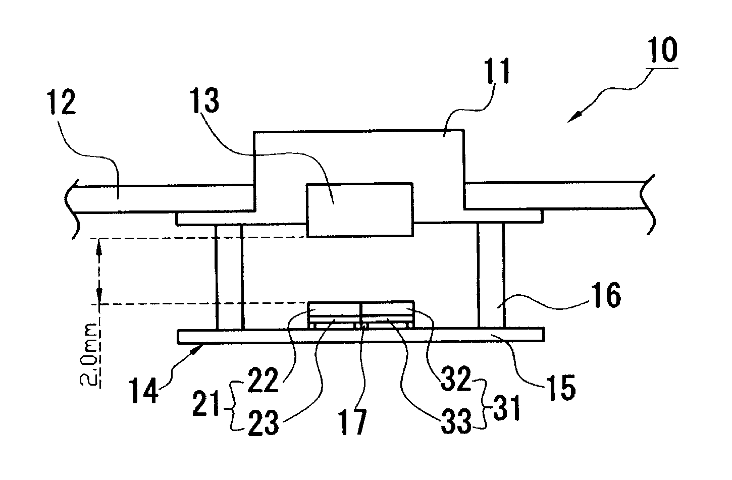
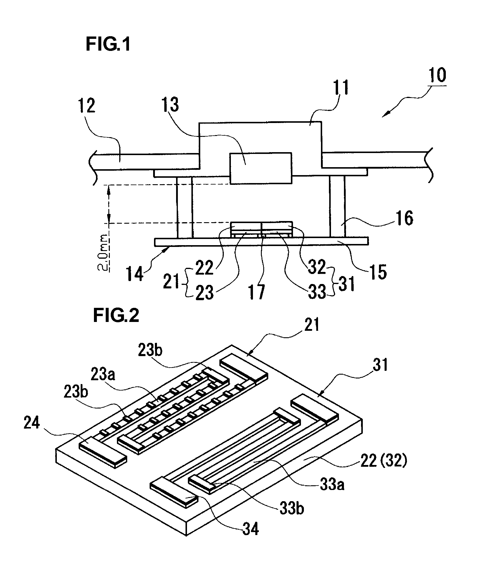
[0027] A multistage switch according to a preferred embodiment of the present invention will be described with reference to FIGS. 1 and 2. The present preferred embodiment will be described in the context of a multistage switch used for a shutter of a camera by way of example.

[0028] A multistage switch 10 shown in FIG. 1 includes a switch push button 11 serving as a shutter release button. The switch push button 11 is surrounded by a housing 12 of the camera, and is generally projected slightly from the housing. A magnet 13 serving as a magnetic member is disposed in a recess of the inner wall surface of the switch push button 11. The magnet 13 is disposed so that lines of magnetic force are generated in the direction in which the switch push button 11 is pressed, i.e., in the direction indicated by an arrow shown in FIG. 1. In th...


PUM


Abstract

A multistage switch includes a switch push button. A magnet is disposed in a recess of the inner wall surface of the switch push button. The multistage switch further includes a magnetic sensor, and the magnetic sensor includes a substrate. Two magnetoelectric transducers are mounted on a surface of the substrate, and are disposed so as to face the magnet.

Description

BACKGROUND OF THE INVENTION [0001] 1. Field of the Invention [0002] The present invention relates to multistage switches. More specifically, the present invention relates to a multistage switch used for a shutter switch of a camera, a photographing switch of a video camera, a switch of other electronic apparatuses, etc., for providing a single switch with a plurality of operation instruction functions. [0003] 2. Description of Related Art [0004] In the related art, multistage switches using disc springs have been generally known (see Japanese Unexamined Patent Application Publication No. 2000-57888). The multistage switches using disc springs function as multistage switches in which a switch push button is pressed by a user so that a plurality of disc springs provided in a multistage switch are sequentially deformed according to the pressing force with which the disc springs are pressed and the operating state of an electronic apparatus is sequentially switched. [0005] The multistag...

Claims


Application Information

Patent Timeline
IPC IPC(8): H01F7/00
CPCG03B9/08H04N5/2251H03K2017/9713H03K17/97
Inventor TOMAKI, KENJINISHIKAWA, MASANAGAUEDA, MASAYA
Owner MURATA MFG CO LTD
Why Eureka
Try Eureka