
Traffic sensor incorporating a video camera and method of operating same

a technology of traffic sensors and video cameras, applied in the field of traffic sensors, can solve the problems of high installation and replacement costs of inductive loop sensors, and inability to operate in the dark or in weather that impairs visibility

Active Publication Date: 2007-11-08
IMAGE SENSING SYSTEMS
View PDF35 Cites 28 Cited by
  • Summary
  • Abstract
  • Description
  • Claims
  • Application Information

AI Technical Summary

Benefits of technology

"The invention provides a method and apparatus for collecting data on vehicular traffic on a road using a traffic sensor. The sensor has both a radar module and an image module, which work together to provide a more complete and accurate understanding of the traffic on the road. The sensor enclosure protects both the radar and image modules. The technical effects of this invention include improved traffic monitoring and analysis, as well as improved safety and efficiency on roads."

Problems solved by technology

Residing underground, inductive loop sensors are expensive to install, replace and repair because of the associated roadwork required.
Moreover, such roadwork also causes traffic disruptions.
Video sensors, on the other hand, are cheaper, but have other drawbacks, such as an inability to operate in the dark or in weather that impairs visibility, such as fog or snow.

Method used


Image

  • Traffic sensor incorporating a video camera and method of operating same
  • Traffic sensor incorporating a video camera and method of operating same
  • Traffic sensor incorporating a video camera and method of operating same

Examples


Embodiment Construction

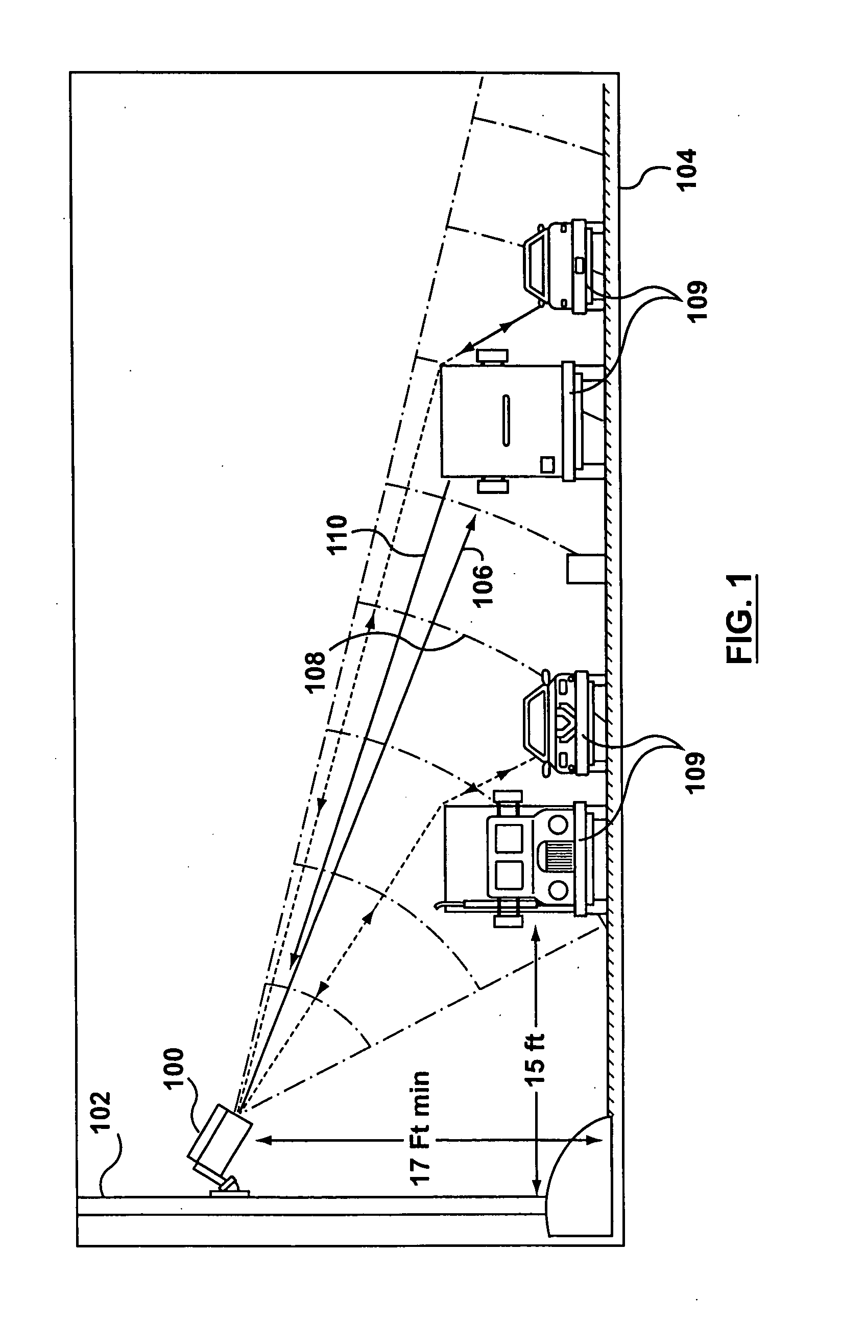
[0018] Referring to FIG. 1, there is illustrated in a schematic view, a sensor 100 in accordance with a preferred aspect of the present invention. The sensor 100 is mounted on a pole 102 in a side-mounted configuration relative to road 104. Sensor 100 transmits a signal 106 through a field of view 108 at the road 104 to “paint” a long elliptical footprint on the road 104. Any non-background targets, such as vehicles 109, reflect a reflected signal Pr 110 having power level P. Specifically, the low-power microwave signal 106 transmitted by sensor 100 has a constantly varying frequency. Based on the frequency of the reflected signal 110, the sensor can determine when the original signal was transmitted, thereby determining the time elapsed and the range to the reflecting object. The range of this reflected object is the “r” in Pr.

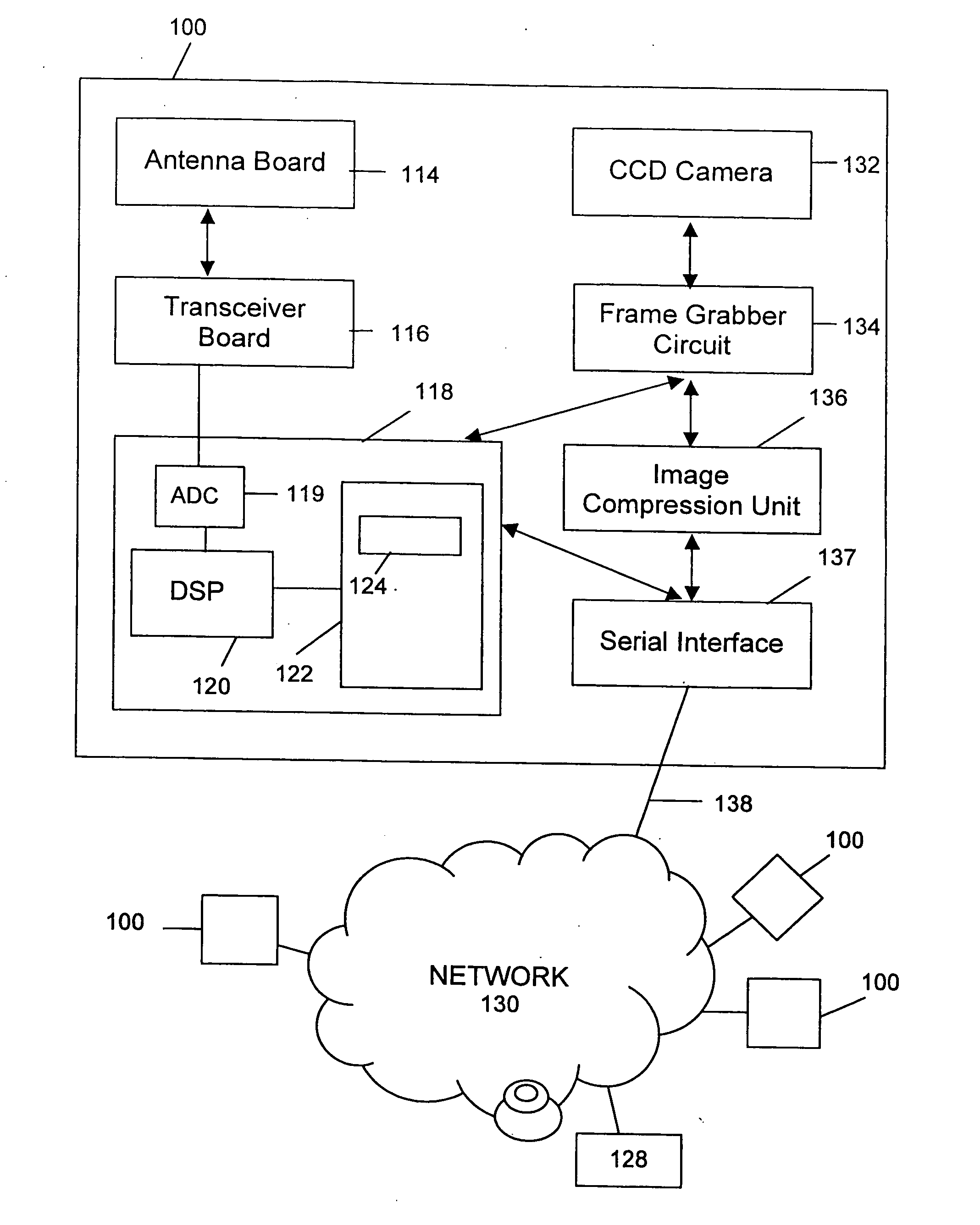
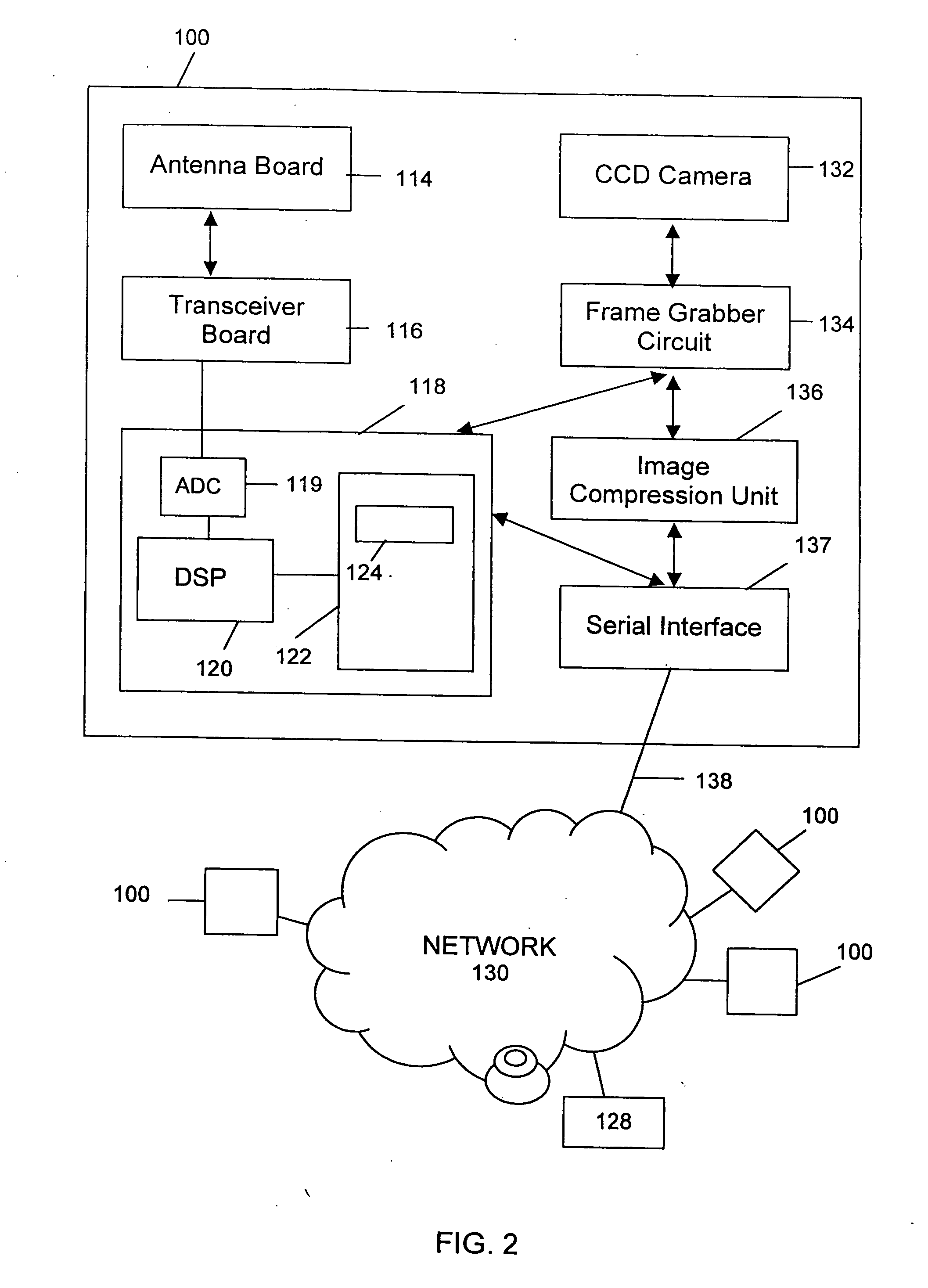
[0019] Referring to FIG. 2, the components of the sensor 100 are illustrated in a block diagram. As shown, the sensor 100 comprises an antenna board 114 for...


PUM


Abstract

A traffic sensor and a method of operating the traffic sensor to collect vehicular traffic data for a road is described. The traffic sensor has (a) a radar module for generating radar-based vehicle data regarding a plurality of vehicles passing the sensor field of view based on detection and measurement of traffic; (b) an image module for generating image data representing a plurality of images of the road and the traffic; and, (c) a traffic sensor enclosure for enclosing both the radar module and the image module.

Description

FIELD OF THE INVENTION [0001] The present invention relates in general to traffic sensors, and more specifically to the verification of the data provided by the sensor through the use of a video camera. BACKGROUND OF THE INVENTION [0002] As urban centers increase in size, and traffic congestion becomes more common, the need for accurate and up-to-date traffic information also increases. Traffic surveillance relies primarily on traffic sensors, such as inductive loop traffic sensors that are installed under the pavement. Alternatively, video sensors may also be used to obtain traffic information. [0003] Residing underground, inductive loop sensors are expensive to install, replace and repair because of the associated roadwork required. Moreover, such roadwork also causes traffic disruptions. Video sensors, on the other hand, are cheaper, but have other drawbacks, such as an inability to operate in the dark or in weather that impairs visibility, such as fog or snow. [0004] To overcome...

Claims


Application Information

Patent Timeline
Patent Type & Authority Applications(United States)
IPC IPC(8): G08G1/01G08B19/00
CPCG01S13/91G01S13/867G08G1/0175G08G1/01
Inventor MANOR, DAN
Owner IMAGE SENSING SYSTEMS
Learn More