Flexible instrument

a flexible, remote control technology, applied in the direction of surgical staples, catheters, surgical forceps, etc., can solve the problems of insufficient satisfaction of current instruments, forceps, scissors, etc., and the inability to control the relatively simple laparoscopic instruments

Inactive Publication Date: 2007-11-08
AURIS HEALTH INC
View PDF99 Cites 87 Cited by
  • Summary
  • Abstract
  • Description
  • Claims
  • Application Information

AI Technical Summary

Problems solved by technology

Although the surgeon can have visual feedback from the surgical site via a video camera or endoscope inserted into the patient, or via radiological imaging or ultrasonic scanning, the ability to control the relatively simple laparoscopic instruments remains difficult.
Even with good visual feedback, the surgeon's tactile and positional senses are physically removed from the operative site, rendering endoscopic procedures slow and clumsy.
Current instrumentation, with forceps, scissors, etc., inserted into the body at the end of long slender push rods is not fully satisfactory.
The use of such conventional instrumentation increases operative time, and potentially heightens risk.
For example, tissue may be injured when the laparoscopic tool moves outside the visual field.
Moreover, there are limitations on the type and complexity of procedures that may be performed laparoscopically due, in part, to the limitations on the instruments that are used.
The known robotic systems are large, clumsy to operate and relatively expensive to manufacture.
The presence of a robot at the surgical site is problematic particularly when the robot is large and may impede access to the patient during surgery.

Method used


Image

  • Flexible instrument
  • Flexible instrument
  • Flexible instrument

Examples


Embodiment Construction

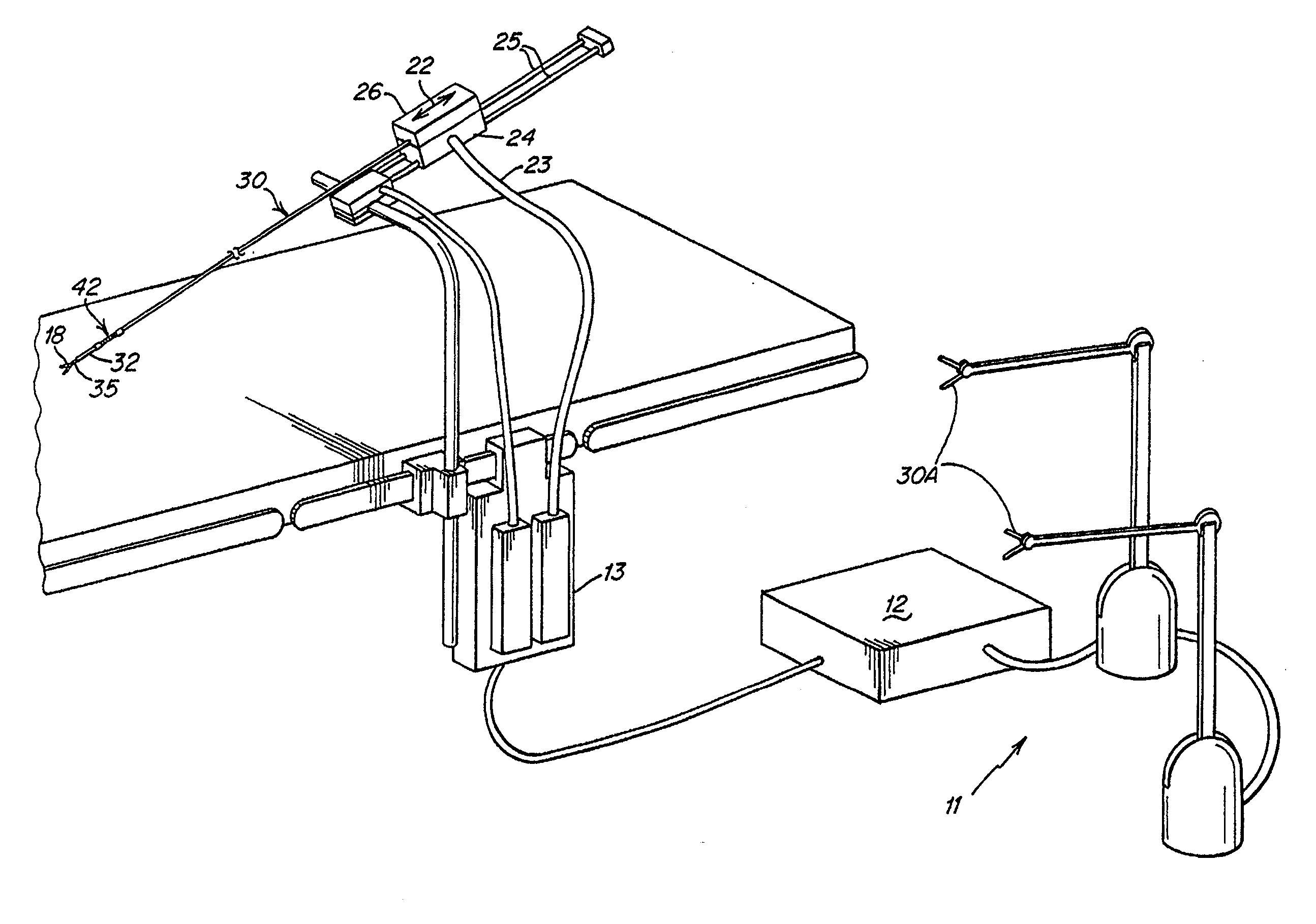
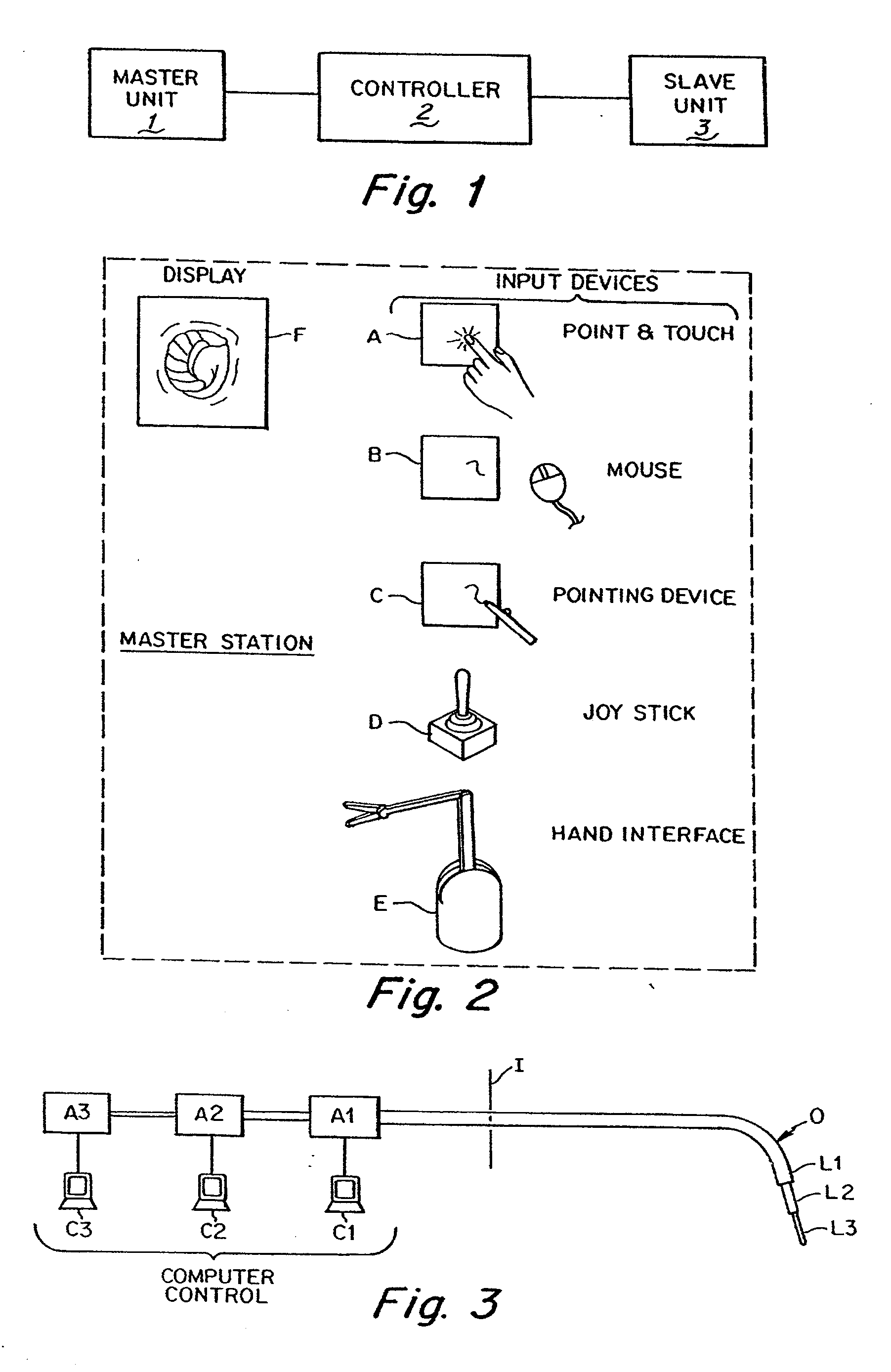
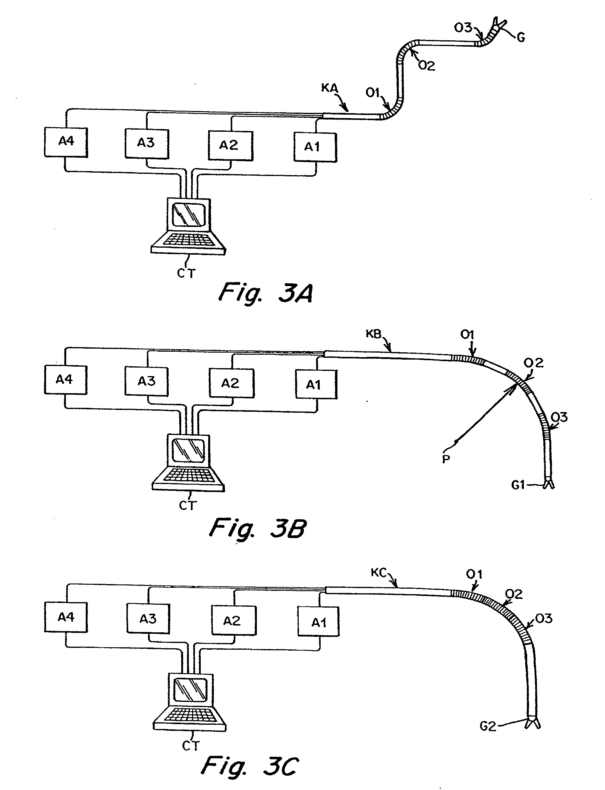
[0072] The present invention provides a system for remotely controlling a flexible instrument for use in medical applications, typically for operative or other medical procedures. The flexible instrument comprises a shaft or a tube of sufficient dimensions for passing through a small incision or natural body lumen or cavity and ultimately, for positioning a distal end of the shaft within the body at an internal target (operative) site. The flexible instrument can also support a tool at its distal end to allow more intricate medical procedures. A user or surgeon can control the position of the shaft from a master station, allowing operation from another part of the operating room, or even from another room or another building. In one aspect of the invention, the shaft can comprise one or more flexible segments, which a user can controllably bend, providing finer control in directing the shaft toward the target site. The control can result in, for example, a deflection or turning of t...


PUM


Abstract

A medical instrument assembly and robotic medical system are provided. The medical instrument assembly comprises an intravascular catheter having an elongated flexible shaft, and a drivable mechanism to which the flexible catheter shaft is mounted. The drivable mechanism has an actuating element configured for effecting movement of the catheter within at least one degree-of-freedom. The medical instrument assembly further comprises a receiver to which the drivable mechanism is configured for being removably mated. The receiver is configured for operably coupling a drive unit to the actuating element. The robotic medical system comprises the medical instrument assembly, a user interface configured for generating at least one command, a drive unit coupled to the receiver, and an electric controller configured, in response to the command(s), for directing the drive unit to drive the actuating element via the receiver to effect movement of catheter to the degree(s)-of-freedom.

Description

CROSS REFERENCE TO RELATED APPLICATIONS [0001] This application is a continuation of U.S. application Ser. No. 10 / 012,586, which is a continuation-in-part of U.S. application Ser. No. 09 / 827,503, filed Apr. 6, 2001 (now U.S. Pat. No. 6,432,112), which is a continuation of U.S. application Ser. No. 09 / 746,853, filed Dec. 21, 2000 (now U.S. Pat. No. 6,692,485), which is a divisional of U.S. application Ser. No. 09 / 375,666 (now U.S. Pat. No. 6,197,017), filed Aug. 17, 1999, which is a continuation of U.S. application Ser. No. 09 / 028,550, filed Feb. 24, 1998 (now abandoned). This application is also a continuation-in-part of U.S. application Ser. No. 09 / 783,637, filed Feb. 14, 2001 (now abandoned), which is a continuation of PCT / US00 / 12553, filed May 9, 2000, which claims the benefit of priority of U.S. application Ser. No. 60 / 133,407, filed May 10, 1999. This application is also a continuation-in-part of PCT / US01 / 11376, filed Apr. 6, 2001, which claims priority the benefit of priority ...

Claims


Application Information

Patent Timeline
Patent Type & Authority Applications(United States)
IPC IPC(8): A61B1/04A61B17/00A61M29/00A61B5/00A61B5/04A61B17/04A61B17/28A61B19/00B25J3/04B25J9/10
CPCA61B5/0084A61B2017/00477A61B5/4893A61B17/00234A61B17/0469A61B17/0483A61B17/29A61B17/3421A61B17/3462A61B19/22A61B19/2203A61B19/50A61B19/52A61B19/5212A61B19/5244A61B2017/00026A61B2017/00088A61B2017/003A61B2017/00331A61B2017/2927A61B2017/2939A61B2019/2211A61B2019/2223A61B2019/223A61B2019/2234A61B2019/2242A61B2019/2246A61B2019/2249A61B2019/2276A61B2019/2284A61B2019/2296A61B2019/265A61B2019/5251A61B2019/5259A61B2019/5276A61B2019/5291B25J3/04B25J9/104A61B5/015A61B2034/715A61B2034/742A61B2034/744A61B2090/506A61B90/36A61B34/20A61B34/70A61B34/71A61B2034/301A61B90/361A61B34/30A61B34/37A61B34/35A61B2034/305A61B34/72A61B34/77A61B34/10A61B2034/2051A61B2034/2059A61B2090/378A61B2090/365A61B17/0487A61B17/0644A61B17/0682A61F2/2445A61F2/2466A61B2017/00243A61B2017/00876A61B2017/00986A61B2017/0409A61B2017/0414A61B2017/0437A61B2017/0464A61B2017/0645A61B2017/0648A61B2017/22069
Inventor BROCK, DAVID L.LEE, WOOJINROGERS, GARYWEITZNER, BARRY
Owner AURIS HEALTH INC
Why Eureka
Try Eureka