Methods and apparatus for estimating engine thrust

a technology for engine thrust and methods, applied in the field of aircraft engines, can solve the problems of engine specific fuel consumption and engine life both being adversely affected, and each of the available known thrust indicators may be subject to errors,

Inactive Publication Date: 2007-11-08
GENERAL ELECTRIC CO
View PDF11 Cites 21 Cited by
  • Summary
  • Abstract
  • Description
  • Claims
  • Application Information

AI Technical Summary

Benefits of technology

[0006] In one aspect, a method for estimating engine thrust is provided. The method includes obtaining information about an initial dynamic state of the engine and updating the information about the initial dyn

Problems solved by technology

Each of the available known thrust indicators may, however, be subject to errors due to random variations in engine-to-engine component quality, deteriora

Method used


Image

  • Methods and apparatus for estimating engine thrust
  • Methods and apparatus for estimating engine thrust
  • Methods and apparatus for estimating engine thrust

Examples


Embodiment Construction

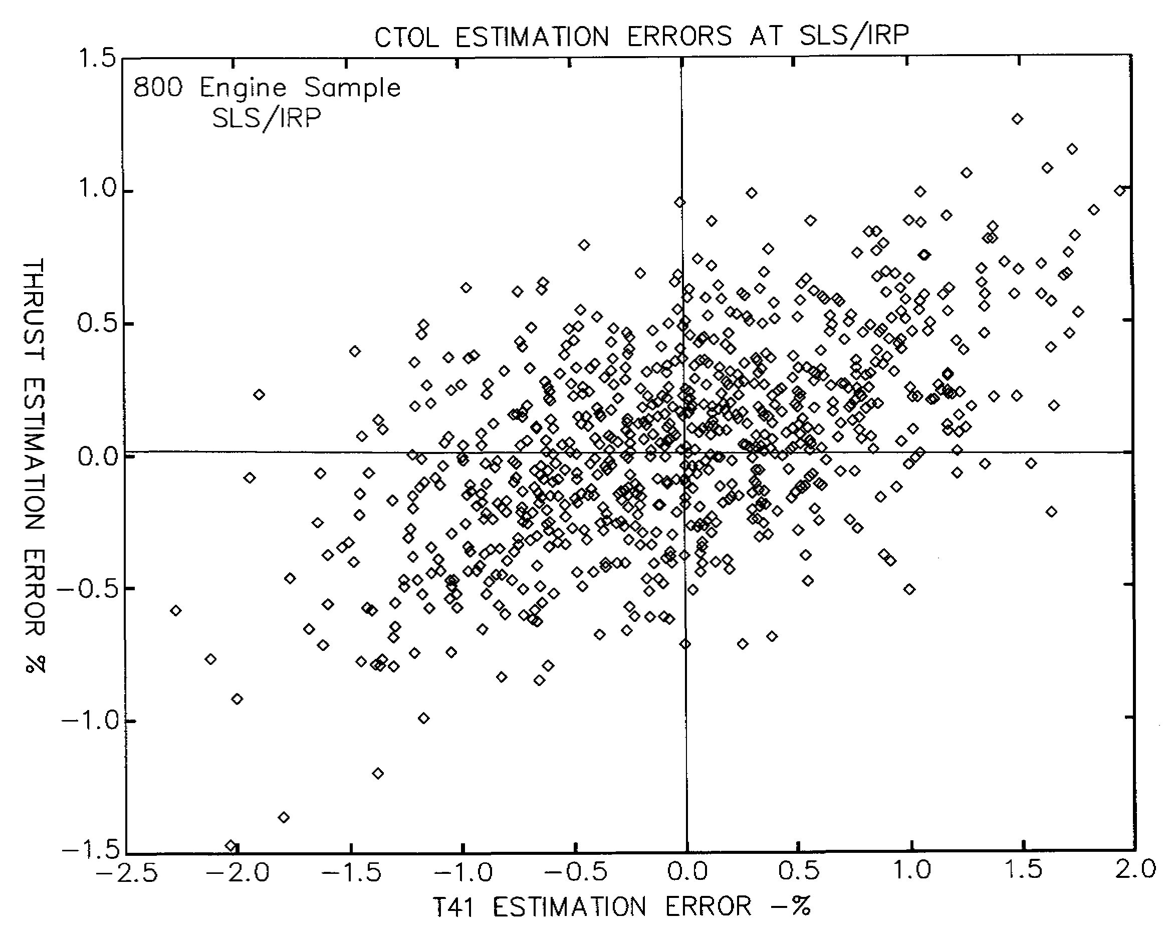
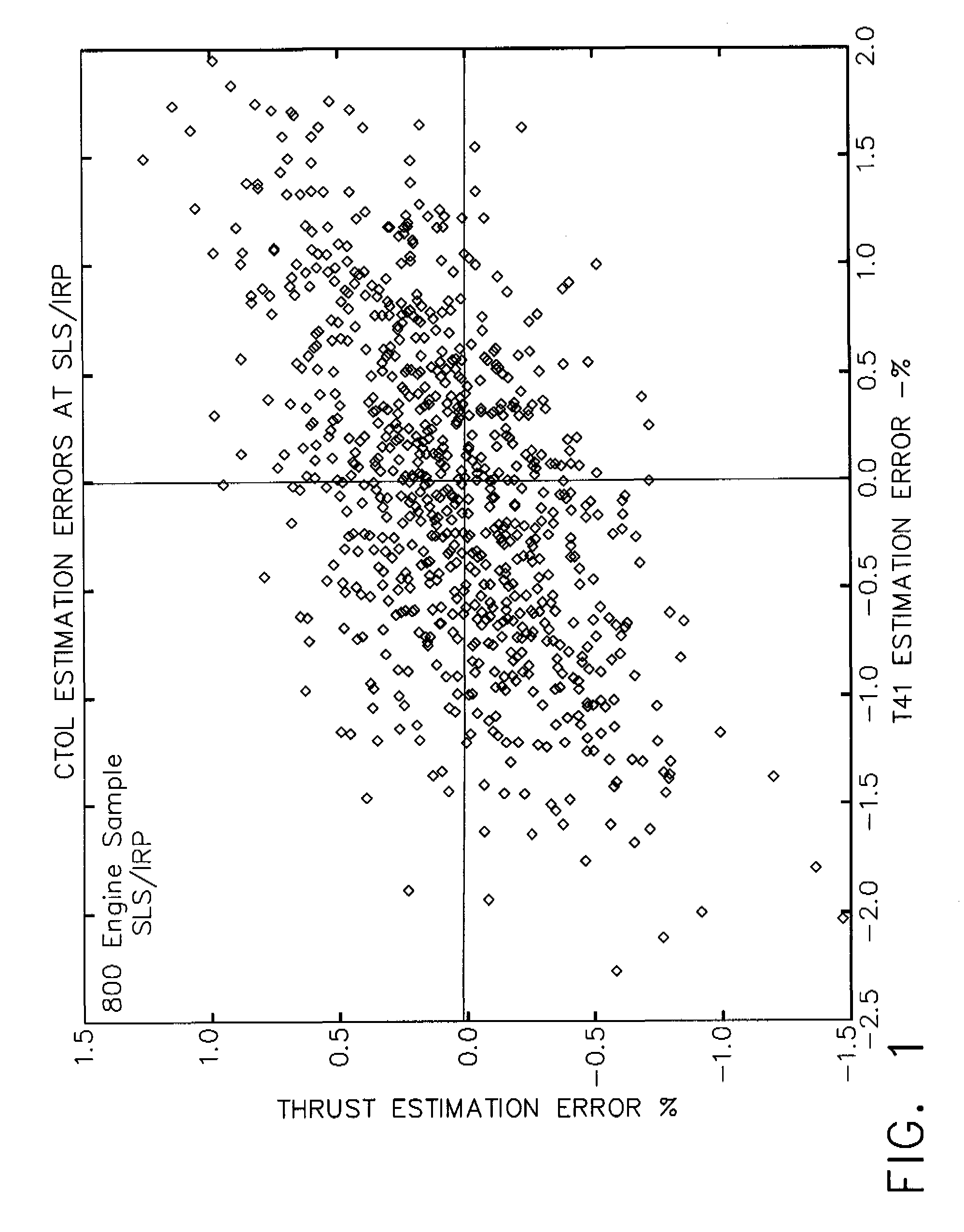
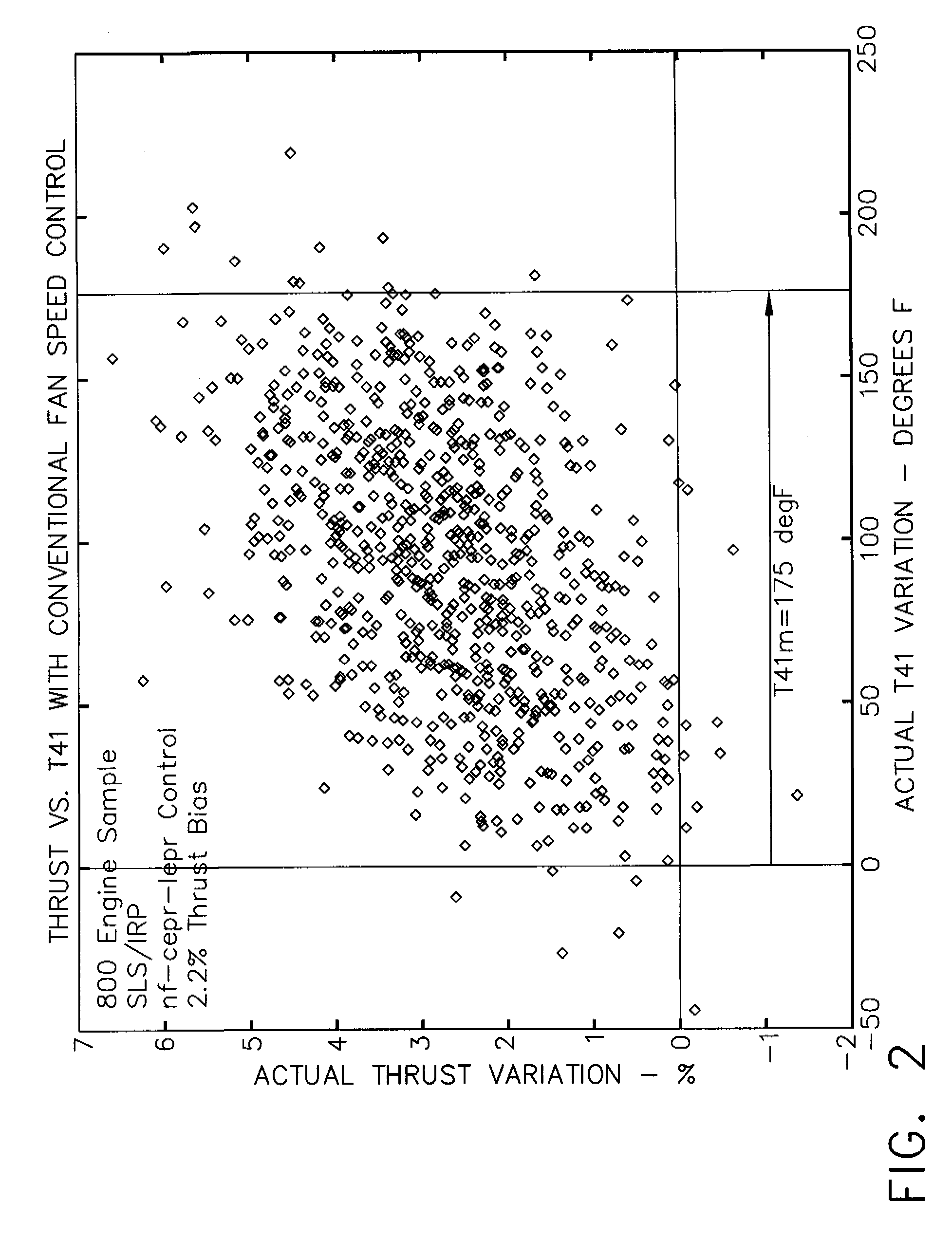
[0012] Known thrust estimators use the available engine to estimate engine thrust and permit engine operation at estimated thrust rather than at a thrust indicator, such as fan speed or engine pressure ratio. It is possible to achieve thrust estimation errors which are substantially smaller than the thrust uncertainties associated with operation at fan speed or engine pressure ratio. This can lead to a substantial reduction in the over-boost and over-temperatures of conventional engine operation.

[0013] A Kalman Filter is an optimal estimation algorithm that accurately estimates system “states”, in the presence of modeling uncertainties and output measurement errors. In this invention, a Kalman Filter has been derived for optimal thrust estimation using the engine thrust (Fn) and HP Turbine Inlet Temperature (T41) as system states.

[0014] The Thrust Estimator has been derived from a linear state-space model of the engine at a specific engine operating condition: [X.Y]=[ABCD]⁡[XU](1...


PUM


Abstract

A method for estimating engine thrust, wherein the method includes obtaining information about an initial dynamic state of the engine and updating the information about the initial dynamic state of the engine to reflect a second dynamic state of the engine. The method also includes generating engine thrust estimates, wherein the thrust estimates facilitate implementing direct thrust control.

Description

STATEMENT REGARDING FEDERALLY SPONSORED RESEARCH & DEVELOPMENT [0001] This invention was made with Government support under contract number JSF N00019-96-C0176. The Government may have certain rights in this invention.BACKGROUND OF THE INVENTION [0002] This invention relates generally to aircraft engines and more particularly, to methods and apparatus for estimating engine thrust. [0003] Engine thrust cannot be measured directly in flight. Since engine thrust cannot be measured, known engines are indirectly controlled via a measurable parameter (such as fan speed or engine pressure ratio, which are good indicators of thrust) in order to meet a specific thrust demand. Each of the available known thrust indicators may, however, be subject to errors due to random variations in engine-to-engine component quality, deterioration, engine sensor errors and actuator position errors. On the other hand, if engine thrust could be estimated accurately, then engine thrust demands could be met pre...

Claims


Application Information

Patent Timeline
IPC IPC(8): G06F19/00G06F17/40
CPCF02C9/28F05D2270/051F05D2270/71
Inventor BROWN, HAROLDDESAI, PREMAL
Owner GENERAL ELECTRIC CO
Why Eureka
Try Eureka