
Apparatus and method for transmitting/receiving data in a communication system

a communication system and apparatus technology, applied in the field of apparatus and methods for transmitting/receiving data in the communication system, can solve the problems of excessive error detection quality of cyclic parity check sum, inability to decode turbo code more effectively than convolutional code, and inability to replace empty frames or frames that do not allow digital to, etc., to achieve the effect of reducing repeated data

Inactive Publication Date: 2007-11-08
SAMSUNG ELECTRONICS CO LTD
View PDF6 Cites 40 Cited by
  • Summary
  • Abstract
  • Description
  • Claims
  • Application Information

AI Technical Summary

Benefits of technology

[0073] Yet another aspect of exemplary embodiments of the present invention provides an apparatus and method for transmitting / receiving data by reducing repeated data in a communication system.

Problems solved by technology

However, it is expedient to replace empty frames or frames that do not allow digital-to-analog conversion.
However, in transmitting data, quality of error detection by the cyclic parity check sum is excessive, considering that an error-resilient Enhanced Variable Rate Codec (EVRC) vocoder is used in data transmission.
However, the turbo code is not more effective than the convolutional code decoded by the Viterbi algorithm, if the size of a data frame created by the vocoder does not exceed 200 bits.
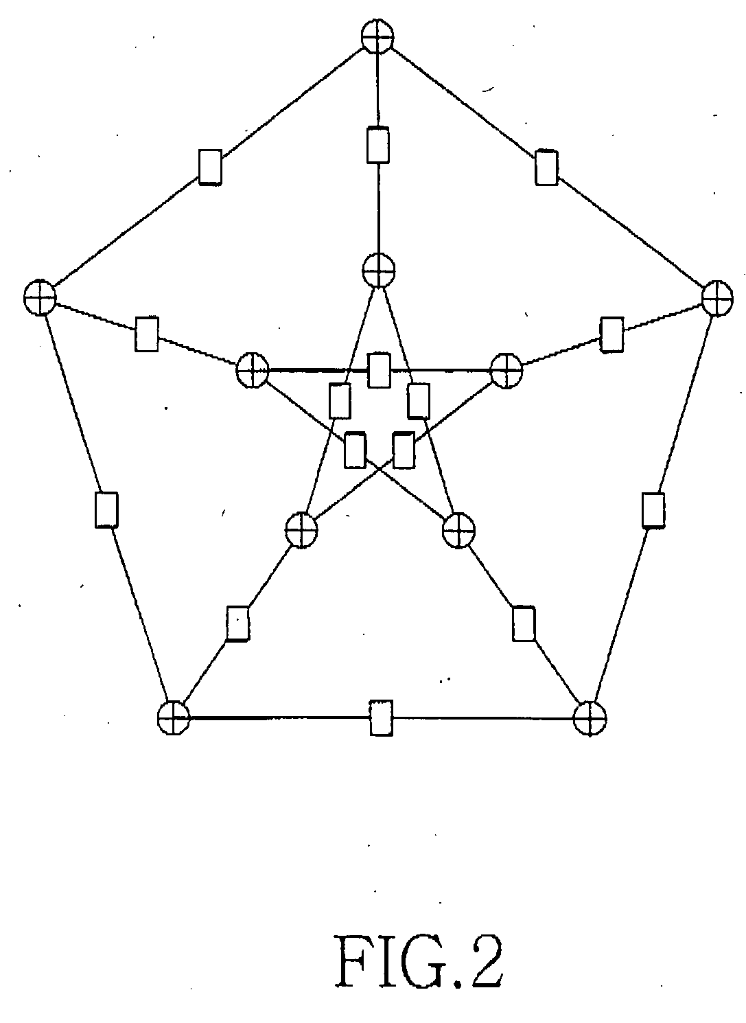
Referring to FIG. 2, the number of vertices is restricted and plotting a graph with more than 100 vertices with preset features is very complex.
If the code is systematic and can be separated into parity check and information components, the above described method has a drawback.
This method does not require the table, but leads to performance degradation even though it reduces the number of decoding operations.
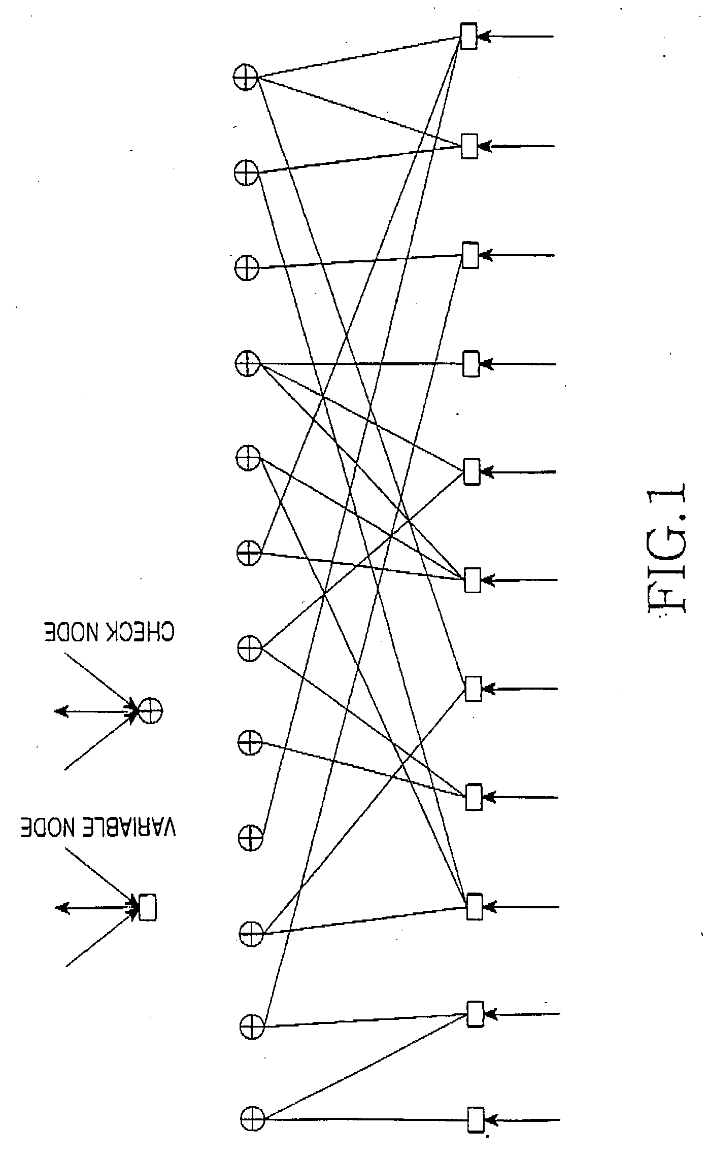
Randomized interleavers present difficulties due to a memory capacity requirement, computation resources, and a computation latency.
In addition, randomized interleavers cannot be generated at the receiver and transmitter sides independently.
However, this method does not guarantee efficiency for a small block size (≦200 bits).
Therefore, it is obvious that both analyzed solutions do not resolve the problem of interleaver optimization in iterative decoding if the data block size is from 10 to 200 bits as they do not provide sufficient spread of the code symbols.
The above conventional coding and interleaving schemes for data transmission are highly complex or are not optimized in performance.
Moreover, with the non-optimized coding and interleaving schemes, efficient error detection and error correction cannot be achieved.

Method used


Image

  • Apparatus and method for transmitting/receiving data in a communication system
  • Apparatus and method for transmitting/receiving data in a communication system
  • Apparatus and method for transmitting/receiving data in a communication system

Examples


Embodiment Construction

[0095] The matters defined in the description such as a detailed construction and elements are provided to assist in a comprehensive understanding of exemplary embodiments of the invention. Accordingly, those of ordinary skill in the art will recognize that various changes and modifications of the embodiments described herein can be made without departing from the scope and spirit of the invention. Also, descriptions of well-known functions and constructions are omitted for clarity and conciseness. Throughout the drawings, the same drawing reference numerals will be understood to refer to the same elements, features and structures.

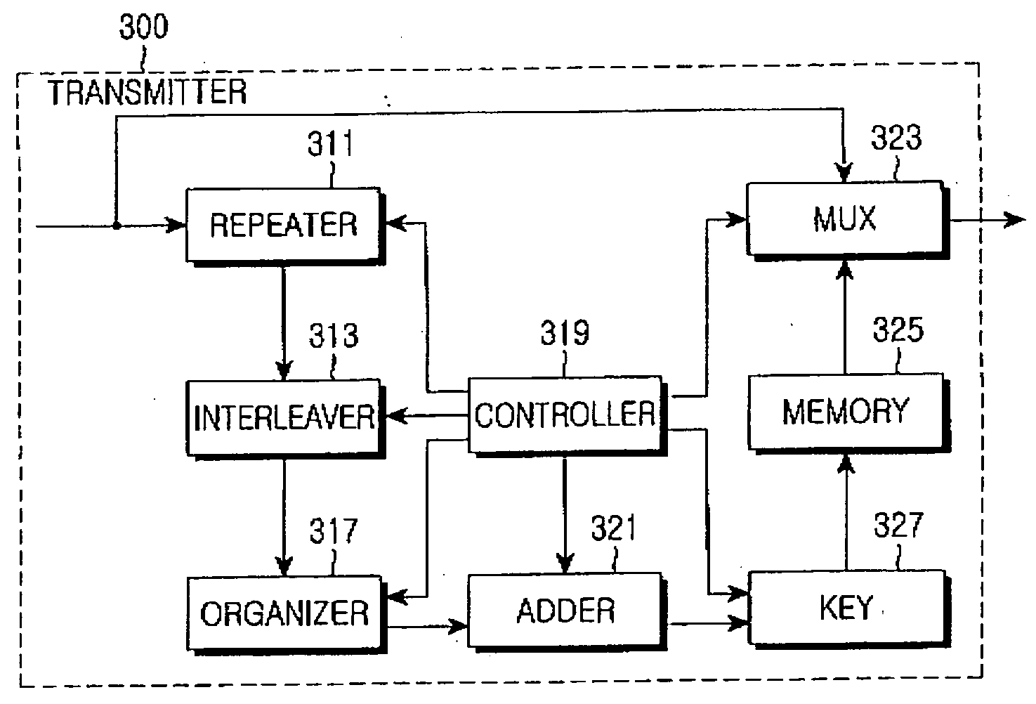
[0096]FIG. 3 is a block diagram of a transmitter for data transmission in a communication system according to an exemplary embodiment of the present invention. Referring to FIG. 3, a transmitter 300 includes a repeater 311, an interleaver 313, an organizer 317, a controller 319, an adder 321, a Multiplexer (MUX) 323, a memory 325, and a key 327. The contr...


PUM


Abstract

An apparatus and method for transmitting / receiving data in a communication system are provided, in which an information symbol is repeated, the repeated information symbols are interleaved, the interleaved repeated information symbols are organized into groups of a predetermined size, an nth parity check matrix is calculated by modulo summation of an (n−1)th parity check symbol and all interleaved repeated information symbols of an nth group, and a codeword is generated by multiplying each of the information symbols by the parity check matrix and transmitting the codeword.

Description

PRIORITY [0001] This application claims priority under 35 U.S.C. § 119(a) to a Russian Patent Application filed in the Russian Federal Institute of Industrial Property on Mar. 21, 2006, and assigned Serial No. 2006108712, the disclosure of which is incorporated herein by reference. BACKGROUND OF THE INVENTION [0002] 1. Field of the Invention [0003] The present invention generally relates to a communication system. More particularly, the present invention relates to an apparatus and method for transmitting / receiving data in a communication system. [0004] 2. Description of the Related Art [0005] In communication systems, data conversion is typically carried out via the following steps: [0006] Analog-to-digital conversion of a transmission signal; [0007] Digital signal transmission across wired networks; [0008] Channel coding; [0009] Code word transmission on a radio channel; [0010] Input signal decoding; [0011] Data signal transmission across wired networks; and [0012] Digital-to-anal...

Claims


Application Information

Patent Timeline
Patent Type & Authority Applications(United States)
IPC IPC(8): G06F13/00
CPCH03M13/1131H03M13/1134H03M13/1137H03M13/3738H03M13/19H03M13/27H03M13/1194H03M13/11H04J13/00
Inventor GARMONOV, ALEXANDER VASILIEVICHCLEVELAND, JOSEPH ROBERTZHDANOV, ALEXANDR EDUARDOVICH
Owner SAMSUNG ELECTRONICS CO LTD
Learn More