Apparatus for Detecting Leakage of Liquid in Tank

a technology for detecting liquid leakage and tanks, which is applied in the direction of liquid transferring devices, fluid tightness measurement, instruments, etc., can solve the problems of increasing error in flow rate measurement valves, liquid in the tank leakage from the tank, and tank cracks may die to time degradation, etc., to suppress errors. detection

Inactive Publication Date: 2007-11-15
MITSUI MINING & SMELTING CO LTD
View PDF2 Cites 7 Cited by
  • Summary
  • Abstract
  • Description
  • Claims
  • Application Information

AI Technical Summary

Benefits of technology

[0032] According to the present inventor, when it is determined in the first step that the absolute value of the liquid quantity variation does not exceed the first predetermined value, the second liquid quantity detection is performed in the second step in which the average absolute value of liquid quantity variations is obtained by time-averaging partial and rapid variations of the liquid level even if they have occurred due to temporary or instantaneous causes such as oscillating liquid in the tank or the like. When it is, determined that this average absolute value of liquid quantity variations exceeds the second predetermined value, the average value of liquid quantity variations relating to the average absolute value of liquid quantity variations is output as a liquid quantity variation, and when it is determined that this average absolute value of liquid quantity variations does not exceed the second predetermined value, the liquid quantity variation obtained by the first liquid quantity variation detection is output. Therefore, erroneous detection is suppressed in leakage detections using a flowmeter. Further, according to the present invention, there can be performed fine and accurate display and warning depending on the degree of increase or decrease in the quantity of the liquid in the tank.

Problems solved by technology

The tank may suffer some cracks die to time degradation.
In this case, liquid in the tank leaks from the tank.
However, in the indirectly heated flowmeter used in the liquid leakage detection apparatus disclosed in the above Patent Document 1, a variation in an electric circuit output level with respect to a variation in a liquid flow rate becomes small in the region where the flow rate value is as infinitesimal as, e.g., 1 milliliter / h or less, so that an error in the flow rate measurement valve tends to increase.
Thus, there is a limit to an improvement in leakage detection accuracy.

Method used


Image

  • Apparatus for Detecting Leakage of Liquid in Tank
  • Apparatus for Detecting Leakage of Liquid in Tank
  • Apparatus for Detecting Leakage of Liquid in Tank

Examples


Embodiment Construction

[0047] Embodiment of the present invention will be described below with reference to the accompanying drawings.

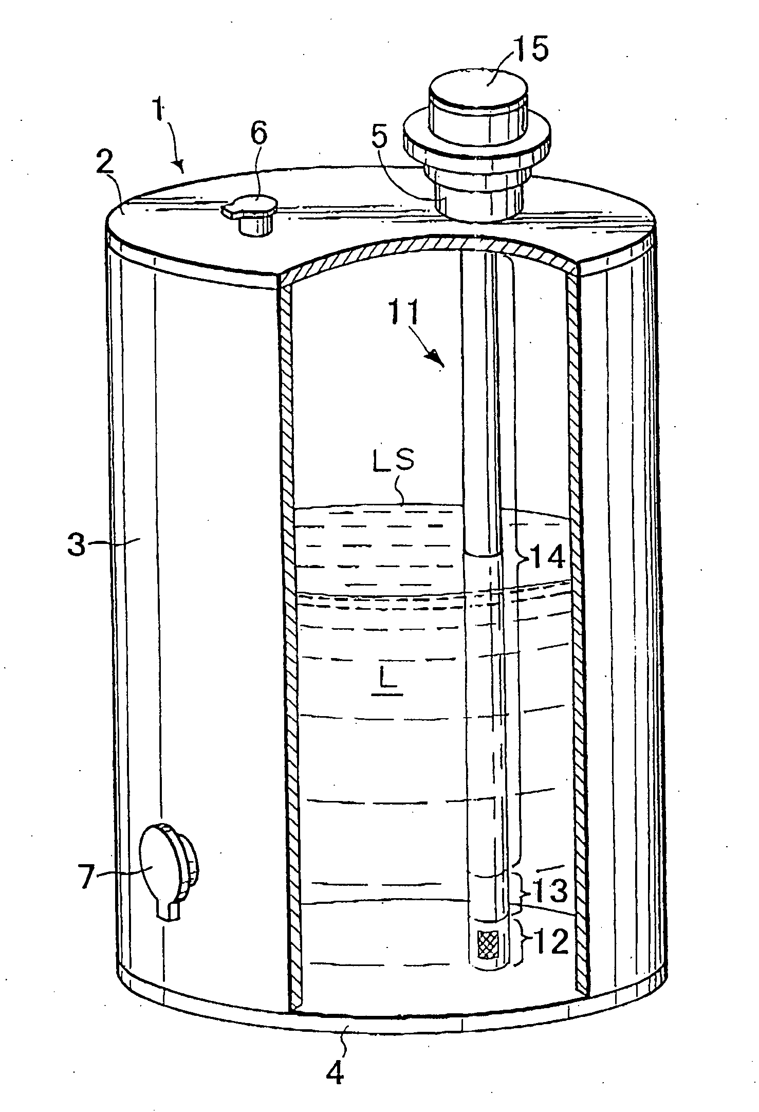
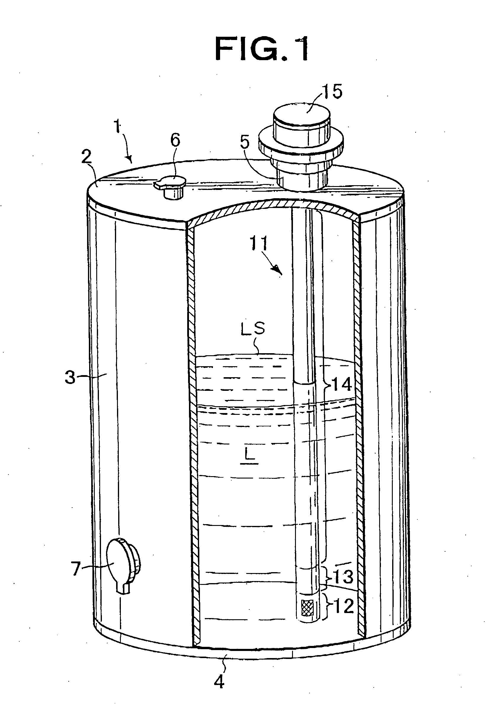
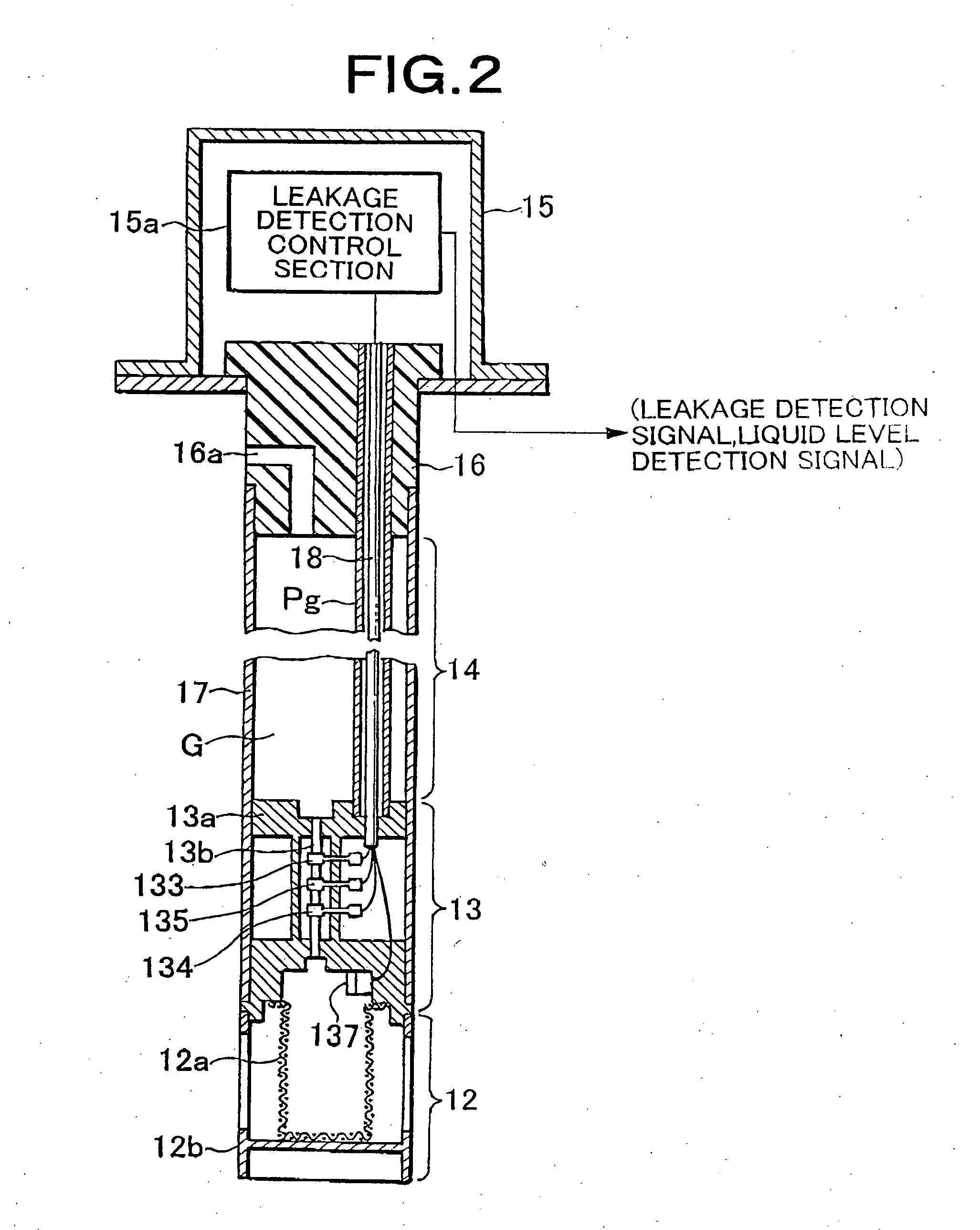
[0048]FIG. 1 is a partially broken view for explaining an embodiment of an apparatus for detecting leakage of liquid in a tank according to the present invention, and FIG. 2 is a partially omitted cross-sectional view of the apparatus for detecting leakage according to the present embodiment.

[0049] A tank 1 has a top panel 2 in which a measurement port 5 and a liquid inlet 6 used when liquid is introduced into the tank are formed, a side panel 3,in which a liquid supply port 7 used when liquid in the tank is supplied to the outside is formed, and a bottom panel 4. As shown in FIG. 1, liquid L (flammable liquid such as gasoline, diesel oil, kerosene, or the like) is contained in the tank 1. IS denotes a liquid surface. A portion of an apparatus for detecting leakage 11 is inserted into the tank 1 through the measurement port 5 formed in the top panel 2 of the tank 1, and t...


PUM


Abstract

A apparatus for detecting leakage of a liquid in a tank, where erroneous detection is suppressed and which is capable of fine and accurate display and warning that depend on the degree of increase and decrease in the quantity of the liquid. The apparatus performs a first liquid quantity variation detection for detecting liquid quantity variation based on a flow rate corresponding value that is calculated using an output of a flow rate sensor section and also performs a second liquid quantity variation detection for detecting liquid quantity variation based on a time variation rate of a liquid level that is measured by the pressure sensor. When it is determined in a first stage (S1) that an absolute value of the liquid quantity variation obtained by the second liquid quantity variation detection does not exceed a first predetermined value (C1), then, in a second stage (S2) after an intermediate stage (Si), an average absolute value of liquid quantity variation is obtained from liquid quantity variations that are obtained by the second liquid quantity variation detection of plural times. After that, when it is determined that the average absolute value exceeds a second predetermined value (C2) that is smaller than the first predetermined value, an average value of liquid quantity variation relating to the average absolute value of liquid quantity variation is outputted as a liquid quantity variation, and when it is determined that the average absolute value does not exceed the second predetermined value (c2), the liquid quantity variation obtained by the first liquid quantity variation detection is outputted.

Description

TECHNICAL FIELD [0001] The present invention relates to an apparatus for detecting leakage of liquid in a tank end, more particularly to, an apparatus for detecting leakage or leak of liquid from a tank by converting it into a flow based on the level variation of liquid in a tank. BACKGROUND ART [0002] Fuel oil or various liquid chemicals are stored in a tank. In recent years, for example, a centralized oiling system for collective housing has been proposed. In this system, kerosene is supplied to the respective homes from a centralized kerosene tank through tubes. [0003] The tank may suffer some cracks die to time degradation. In this case, liquid in the tank leaks from the tank. It is very important to detect such leakage as soon as possible and cope with it adequately for preventing explosion and fire hazard, ambient pollution, or generation of poisonous gas. [0004] As an apparatus for detecting leakage of liquid in a tank in the shortest possible time, JF-A-2003-185522 (Patent D...

Claims


Application Information

Patent Timeline
Patent Type & Authority Applications(United States)
IPC IPC(8): G01M3/26B67D7/32
CPCB65D90/50B67D7/3209G01M3/3254G01M3/3245G01M3/3236B65D90/51
Inventor KOIKE, ATSUSHIMAKINO, TSUTOMU
Owner MITSUI MINING & SMELTING CO LTD
Why Eureka
Try Eureka