
Synchronization signal detector, information recording/reproducing apparatus, and synchronization signal detecting method

a technology of synchronization signal and detector, applied in the direction of synchronization signal speed/phase control, digital signal error detection/correction, instruments, etc., can solve the problems of greater probability, burst error, and temporary inability to detect synchronization signals, so as to reduce the time required for re-detecting synchronization signals, the possibility of synchronization signal detection is improved, and the synchronization signal detection is suppressed.

Inactive Publication Date: 2005-09-29
RENESAS ELECTRONICS CORP
View PDF2 Cites 8 Cited by
  • Summary
  • Abstract
  • Description
  • Claims
  • Application Information

AI Technical Summary

Benefits of technology

[0039] In accordance with the present invention, a dual pattern detection area of a synchronization signal detecting circuit is adopted, erroneous detection of the synchronization signal is suppressed, the possibility of synchronization signal detection is improved and the time required for re-detecting the synchronization signal is shortened.

Problems solved by technology

However, there are cases where the synchronization signal present in the area in which recording has already been performed is not adopted as the reference.
If the shift in recording becomes large, regardless of whichever of the above is the cause, detection of the synchronization signal becomes temporarily impossible and this results in burst error.
As a result, there is a greater probability that the synchronization signal will be detected erroneously.
However, there is absolutely no description concerning a method of generating a synchronization signal that deals with a shift in recording.
Consequently, it takes time to detect a synchronization signal that has deviated owing to a recording shift.

Method used


Image

  • Synchronization signal detector, information recording/reproducing apparatus, and synchronization signal detecting method
  • Synchronization signal detector, information recording/reproducing apparatus, and synchronization signal detecting method
  • Synchronization signal detector, information recording/reproducing apparatus, and synchronization signal detecting method

Examples


Embodiment Construction

[0048] Preferred modes for carrying out the present invention will be described below.

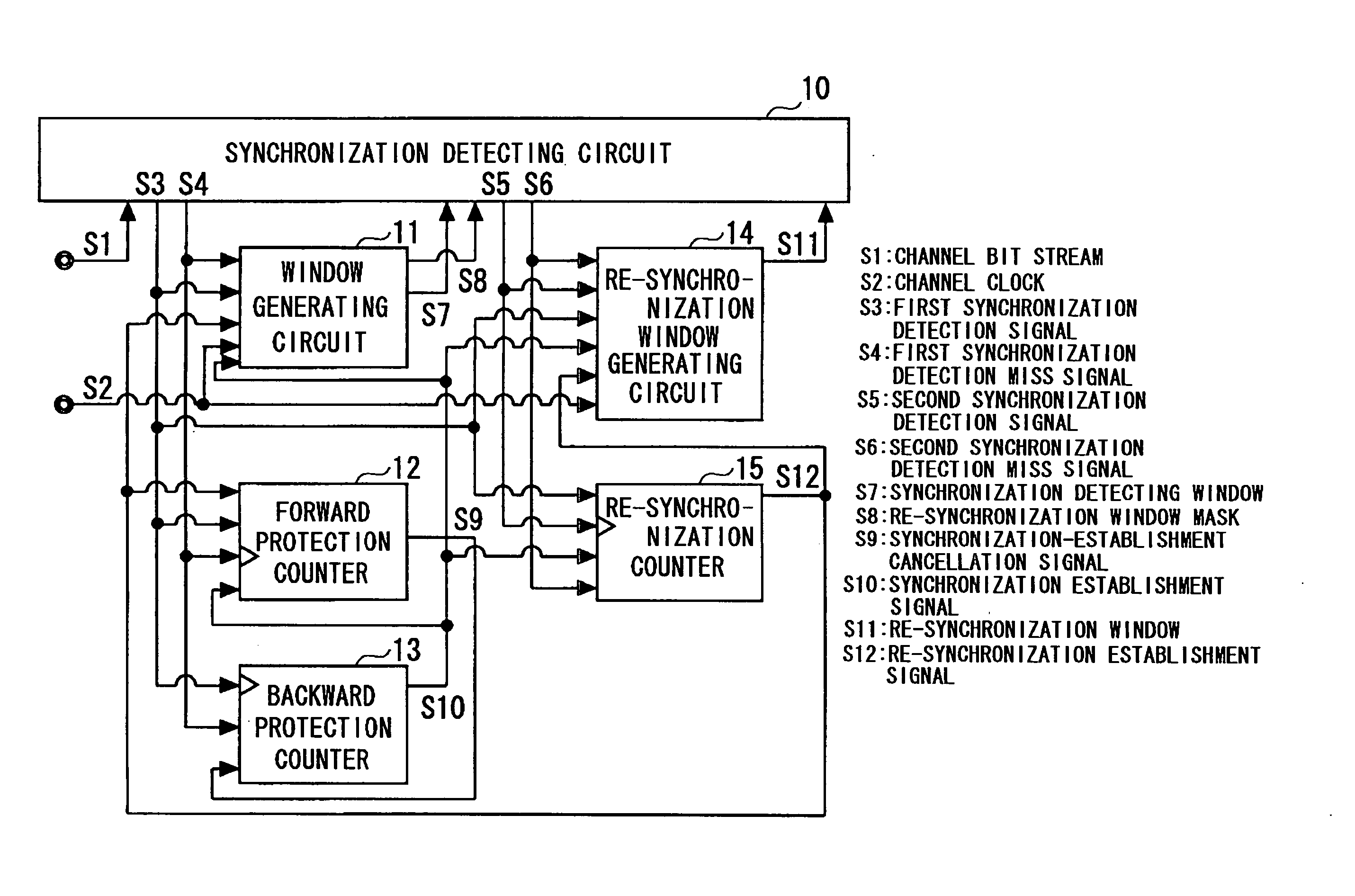
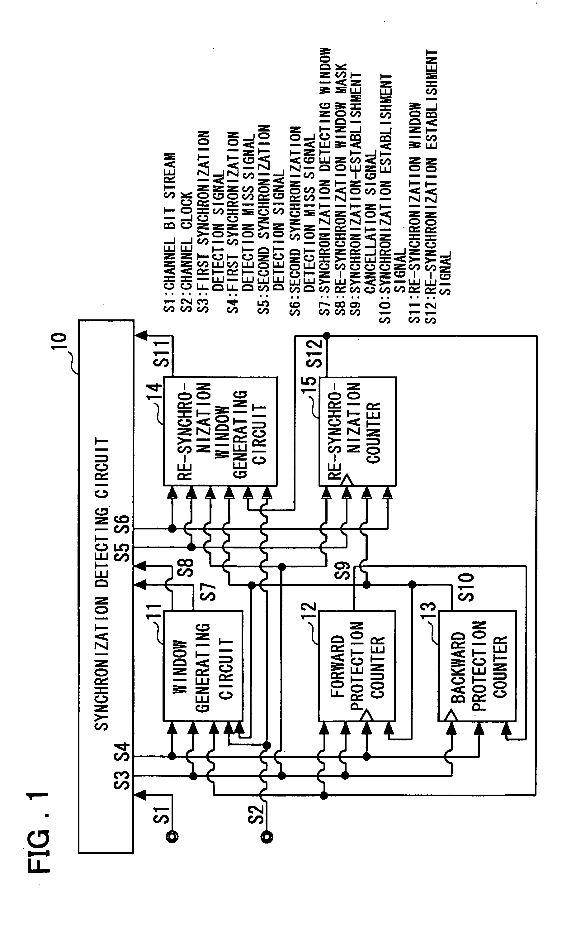
[0049] A synchronization signal detector according to a preferred mode for carrying out the present invention uses dual windows to solve the problem of the prior art that arises at read-out of data from a disk in which a recording shift, for example, has occurred. In this mode of practicing the invention, in addition to a circuit (11 in FIG. 1) that generates a window for detecting synchronization, a circuit (14 in FIG. 1) for generating a re-synchronization window is provided and it is so arranged that a synchronization signal that has shifted greatly from the synchronization detecting window owing to a recording shift or the like is detected by the re-synchronization window.

[0050] More specifically, a synchronization signal detector according to a preferred mode for carrying out the present invention includes a window generating circuit (11 in FIG. 1) for generating a synchronization detecting ...


PUM

PropertyMeasurementUnit
timeaaaaaaaaaa
time intervalaaaaaaaaaa
length of timeaaaaaaaaaa

Abstract

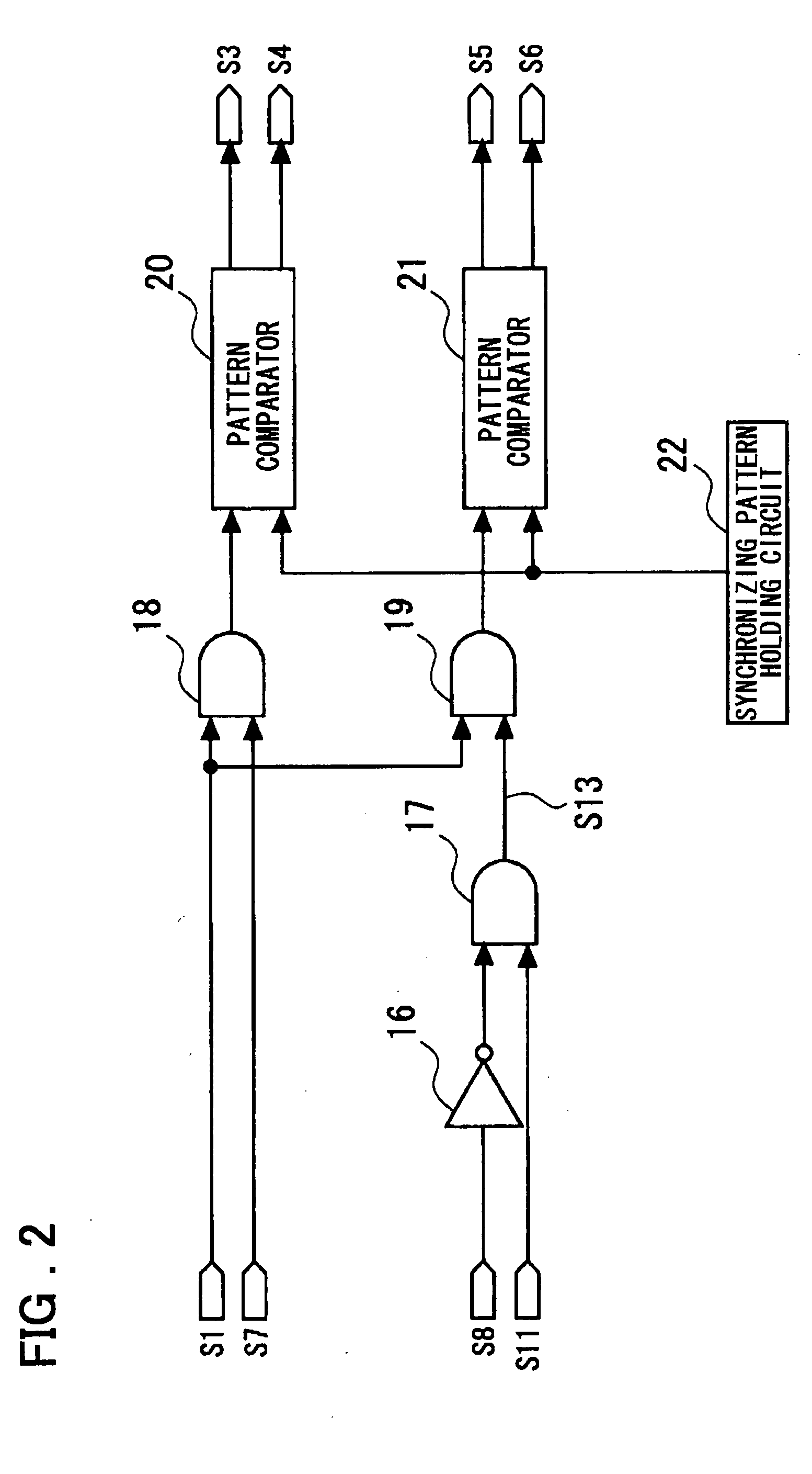
Disclosed is a synchronization signal detecting apparatus that includes a window generating circuit for generating a synchronization detecting window, a re-synchronization window generating circuit for generating a re-synchronization window, and a synchronization detecting circuit for generating a re-synchronization detecting window of a time interval that excludes a re-synchronization window mask from the re-synchronization window, detecting a synchronization signal from an input bit stream and detecting the synchronization signal in the re-synchronization detecting window. If the synchronization signal is detected in the re-synchronization detecting window without being detected in the synchronization detecting window a prescribed number of times in succession, the time interval of the re-synchronization window is updated. If the synchronization signal is detected in the re-synchronization window a prescribed number of times in succession, a re-synchronization counter outputs a re-synchronization establishment signal, the window generating circuit resets the position of the synchronization detecting window and generates the synchronization detecting window at a predetermined synchronization period, and the re-synchronization window generating circuit resets the re-synchronization window.

Description

FIELD OF THE INVENTION [0001] This invention relates to a synchronization detecting circuit and, more particularly, to a synchronization signal detecting device and method ideal for application to an information recording / reproducing apparatus such as an optical disk, an information reproducing apparatus and an information recording / reproducing apparatus. BACKGROUND OF THE INVENTION [0002] When information is recorded on an optical disk such as a DVD (Digital Versatile Disk) or the like, a synchronization signal (SYN), which is a predetermined specific bit pattern, is written to the optical disk together with data at a fixed period in accordance with a recording format in order that the data may be read out. FIG. 5 illustrates an example of the format of a sector on an optical disk such as a DVD. In the example shown in FIG. 5, there are 13 rows, which are obtained by adding one row of an external parity code to a 182-byte, 12-row sector, where the 182 bytes are obtained by adding a...

Claims


Application Information

Patent Timeline
Patent Type & Authority Applications(United States)
IPC IPC(8): G11B20/14G11B7/00G11B20/10G11B20/18H04L7/00H04L7/04
CPCH04L7/042G11B20/10009G11B20/10
Inventor SHIN-E, HIROYUKI
Owner RENESAS ELECTRONICS CORP
Learn More