
Liquid container

Inactive Publication Date: 2007-11-15
CANON KK
View PDF6 Cites 20 Cited by
  • Summary
  • Abstract
  • Description
  • Claims
  • Application Information

AI Technical Summary

Benefits of technology

[0009]The present invention provides a liquid container that can actively generate a flow for efficiently stirring a liquid, such as pigment ink or the like, contained therein.
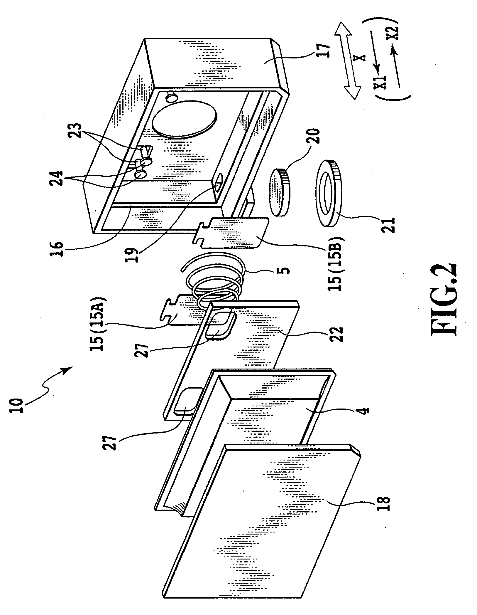
[0013]According to the aspects of the invention, when a plurality of stirring members in the liquid container move by the inertial force according to the movement of the carriage, the individual stirring members make different moves. As a result, the flow of the liquid can be actively generated between the stirring members. With the flow of the liquid generated between the stirring members, a difference in concentration distribution of the liquid in the liquid container can be improved.

Problems solved by technology

In this state, when the pigment ink is supplied from the ink tank to print an image, the pigment concentration of the pigment ink to be supplied is ununiform, and density unevenness may occur in the printed image.
Further, when the pigment ink having extremely high pigment concentration is supplied to a printing head, the coagulated pigment may be clogged in a flow passage of the printing head, and the ink cannot be ejected from the printing head.

Method used


Image

  • Liquid container
  • Liquid container
  • Liquid container

Examples


first embodiment

[0046]A liquid container of this embodiment is an ink tank, which contains pigment ink, for a serial scan type ink jet printing apparatus.

[0047]FIG. 11 is a perspective view of such an ink jet printing apparatus. The printing apparatus includes an apparatus main body 100, a feed unit 101, and a discharge tray 102. In the apparatus main body, as shown in FIG. 12, a chassis 104 and various printing operation mechanisms are provided. A printing head cartridge (not shown) is detachably mounted on a carriage 103, which moves in a main scanning direction (a direction of an arrow X), to perform printing on a printing medium.

[0048]Upon printing, the printing head cartridge moves in the main scanning direction along with the carriage and ejects ink from a printing head.

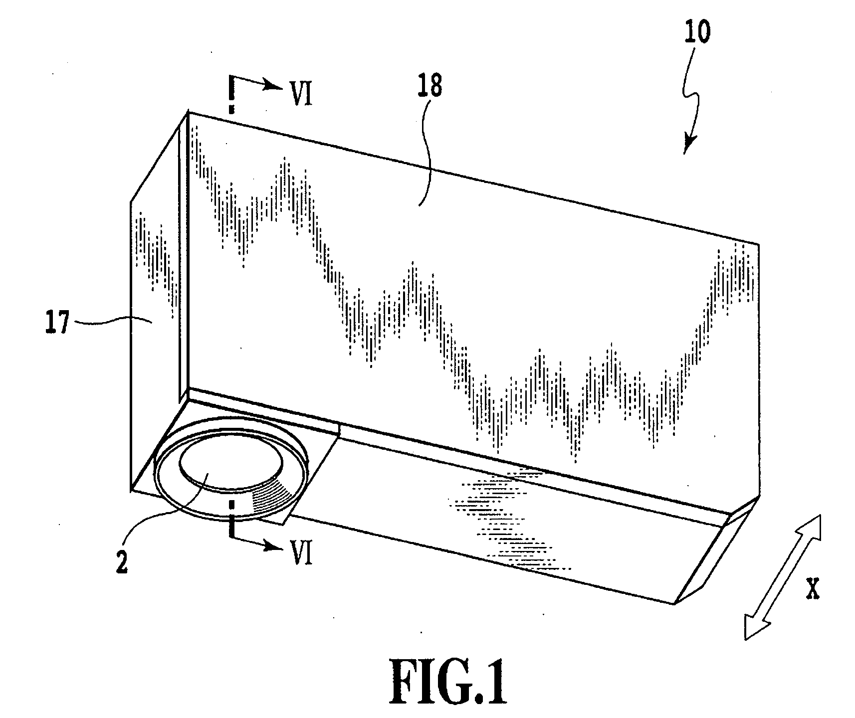
[0049]FIG. 1 is a perspective view of an ink tank 10 that constitutes a printing head cartridge together with a printing head. The ink tank of this embodiment includes a container main body 17 and a cover member 18. A containi...

second embodiment

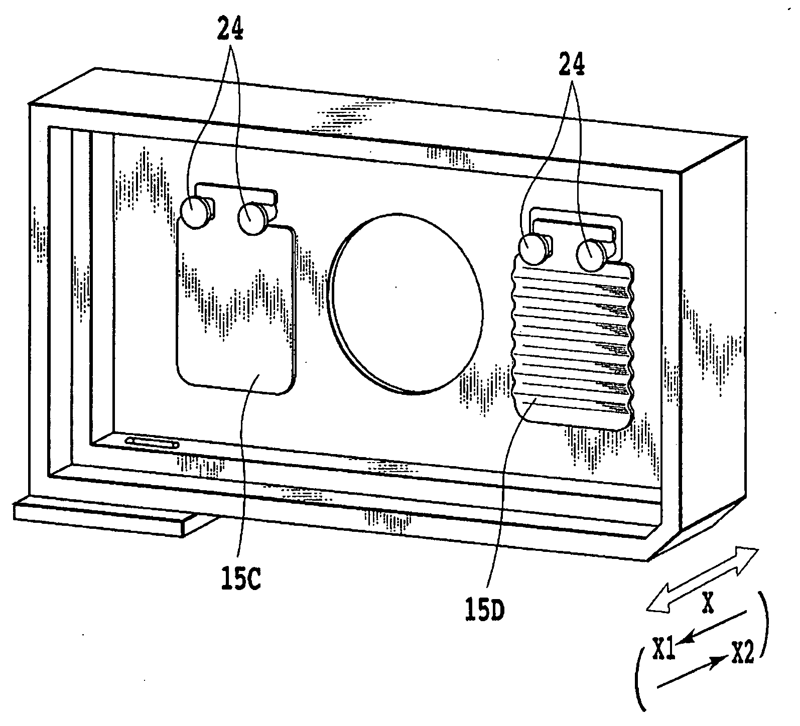
[0079]FIG. 10 is a perspective view of the essential parts of an ink tank according to a second embodiment of the invention.

[0080]The ink tank of this embodiment includes two stirring members 15C and 15D substantially having the same weight and size. The inertial moments of the stirring members 15C and 15D are substantially the same. A stirring surface of the stirring member 15C is flat, and a stirring surface of the stirring member 15D is wavy to increase the surface area. Accordingly, during the stirring operation, the stirring member 15D is subject to resistance from ink larger than the stirring member 15C does. For this reason, when the areas of the stirring surfaces of the stirring members 15C and 15D are Sa and Sb, and the inertial moment of each of the stirring members 15C and 15D is I, ratios I / Sa and I / Sb are different from each other. Further, when the mass of each of the stirring members 15C and 15D is M, ratios M / Sa and M / Sb are different from each other.

[0081]In this em...


PUM


Abstract

An ink tank includes two stirring members having different masses in an ink containing chamber. The two stirring members are moved by an inertial force according to movement of a carriage and stir ink. The two stirring members have different movement start times and movement speeds.

Description

BACKGROUND OF THE INVENTION[0001]1. Field of the Invention[0002]The present invention relates to a liquid container that stores various liquids, such as ink and the like, and uniformizes the components of the liquid. In particular, the invention relates to a liquid container that is suitably used as an ink tank containing pigment ink for an ink jet printing apparatus.[0003]2. Description of the Related Art[0004]There is known an ink jet printing apparatus that performs printing by using pigment ink. The pigment ink contained in an ink tank is supplied from the ink tank to the ink jet printing apparatus that can eject ink. In the pigment ink, a pigment is used as a colorant, and the pigment is dispersed in an ink solvent.[0005]A printing medium on which an image is printed by using the pigment ink has excellent light resistance and water resistance. In the pigment ink, the pigment itself is dispersed in the ink solvent as particles. Accordingly, when an ink tank (liquid container) th...

Claims


Application Information

Patent Timeline
IPC IPC(8): B41J2/19
CPCB01F11/0022B41J2/17513B01F11/04B01F31/24B01F31/42
Inventor IIJIMA, YASUSHIKAWAMURA, SHOGOKOTAKI, YASUOINOUE, RYOJIOGURA, HIDEKIOHASHI, TETSUYA
Owner CANON KK
Learn More