Superconductive non-contact rotary device

a rotary device, superconductive technology, applied in the direction of magnetic holding devices, machines/engines, positive displacement liquid engines, etc., can solve the problems of magnetic decoupling, operation interruption, and use of magnetic coupling between magnets, so as to prevent material contamination, high speed, and efficiently stir

Inactive Publication Date: 2007-04-12
MAGUNEO
View PDF6 Cites 11 Cited by
  • Summary
  • Abstract
  • Description
  • Claims
  • Application Information

AI Technical Summary

Benefits of technology

[0039] According to the present invention, the superconductivity phenomenon can be utilized to make a rotary body rotate in a non-contact state, so that various solutions can be stirred while preventing contamination of the material due to rotation in a contact state. Further, according to the present invention, a rotary body can be rotated in a non-contact state at a high speed while suppressing precessional motion, and solutions can be efficiently stirred while preventing contamination of the material.

Problems solved by technology

The problem in the conventional system lies in the utilization of the magnetic coupling between the magnets.
For this reason, if it were possible to realize a non-contact rotation mechanism by using the magnetic coupling between the superconductor and the magnet alone, the problem of the magnetic de-coupling and the operation interruption.

Method used


Image

  • Superconductive non-contact rotary device
  • Superconductive non-contact rotary device
  • Superconductive non-contact rotary device

Examples


example 1

[0068] Example 1

[0069] As a superconductor, an Sm—Ba—Cu—O-based superconductor having a diameter of 45 mm and a height of 15 mm was used. The superconductor was fabricated by the following procedure.

[0070] A powder material comprised of SmBa2Cu3Oy and Sm2BaCuO5 mixed in a ratio of 3:1, Ag2O added in an amount of 10 mass %, and Pt added in an amount of 0.5 mass % was sufficiently mixed by a mortar and pestle, then was shaped by a uni-axial press and further shaped by cold isostatic pressing under a pressure of 200 MPa to prepare a precursor.

[0071] This precursor was heated in the air to 1100° C. and cooled to 1050° C. at a rate of 50° C. / h, then an NdBa2Cu3Oy single crystal was placed on the precursor as a seed crystal. The precursor was gradually cooled at a cooling rate of 0.5° C. / h to 900° C. to cause crystallization, was then furnace-cooled to room temperature. After furnace cooling, the crystal was annealed in flowing oxygen at 400° C. for 100 hours to impart a superconductive...

example 2

[0083] Example 2

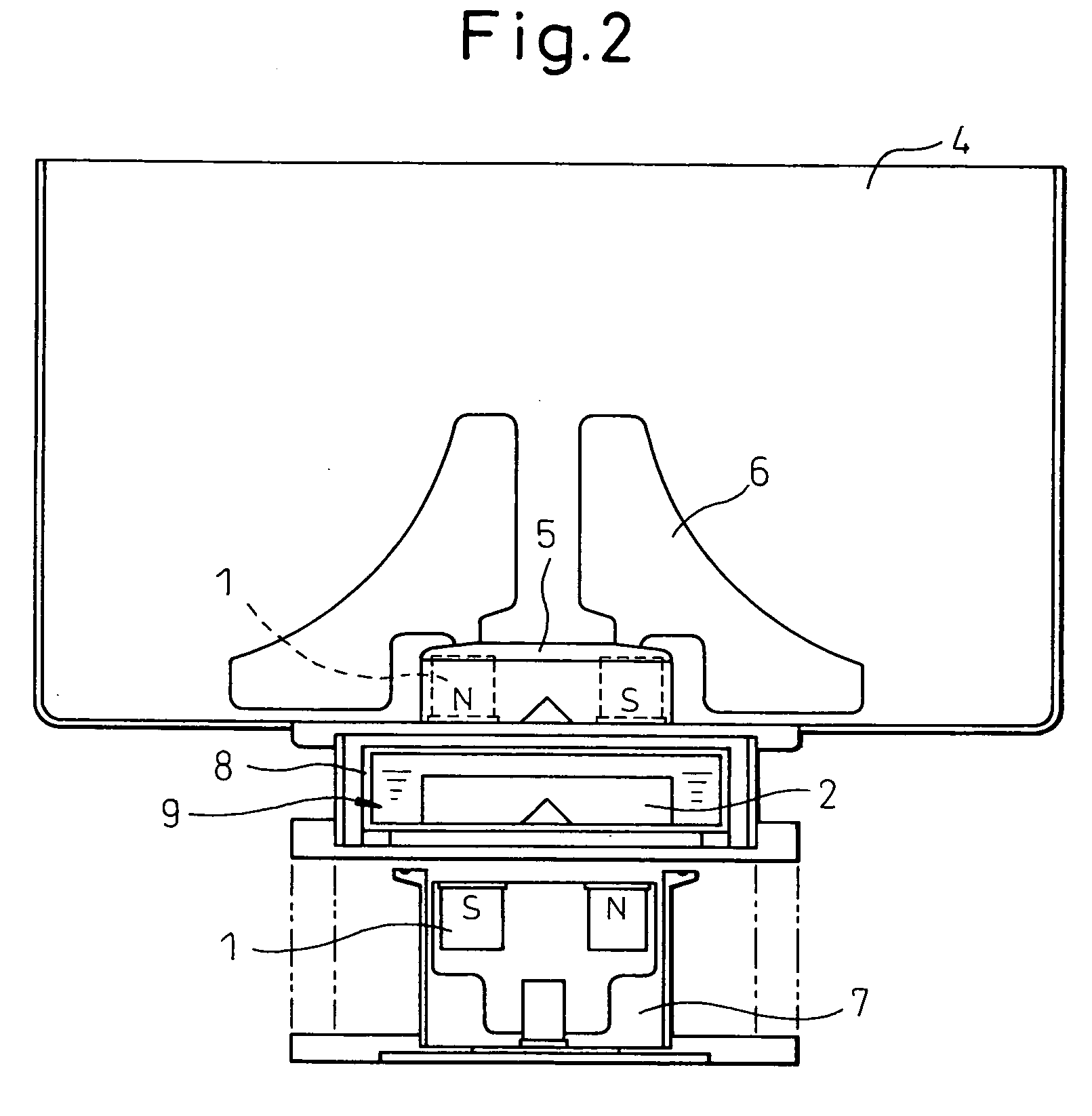
[0084] In the process of repeating the stirring experiment of Example 1, it was learned that at the time of setting, the upper and lower magnets interact. This is because at the start of the setting, the superconductor present between one magnet and the other is normal conducting and does not exhibit any magnetic shield effect. Due to such interaction, the upper and lower magnets sometimes could not be stabilized at a predetermined position and inclined.

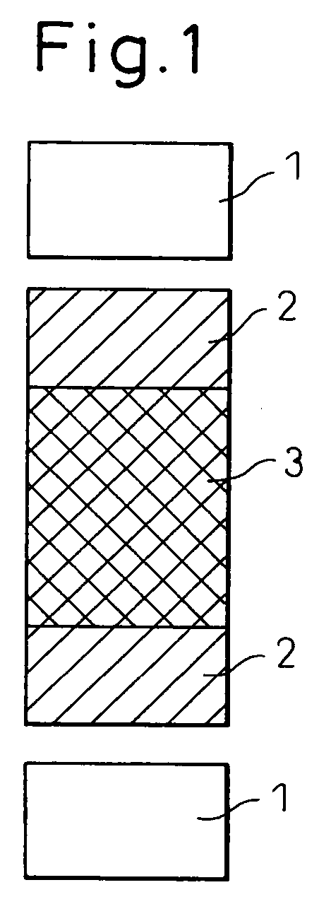
[0085] Therefore, to reduce this interaction, the inventors experimented with increasing the distance between magnets. As one experiment, an epoxy plastic cylinder was inserted between the two superconductors (see FIG. 1).

[0086] As the superconductors, two commercially available Y—Ba—Cu—O-based superconductors having diameters of 45 mm and heights of 15 mm were used. As the permanent magnets, two permanent magnets the same as those used in Example 1 were used.

[0087] One magnet was covered with aluminum and given bl...

example 3

[0096] Example 3

[0097] In the stirring device of Example 2, the blades rotated tracking the other magnet up to a rotational speed of 20 rpm, but were slightly delayed in rotation at greater rotational speeds. This is because the magnetic coupling between the superconductor and magnets was insufficient, the torque was insufficiently transmitted, and the viscosity resistance of water caused a delay in the rotation.

[0098] A superconductor is paramagnetic above the critical temperature, so the magnetic fields formed by the permanent magnets pass through the superconductor as they are, but when the superconductor were to include a ferromagnetic material (for example, iron) inside it, the magnetic fields would concentrate at the ferromagnetic material.

[0099] If making the superconductor superconductive in the concentrated state of this magnetic field, the magnetic field is fixed in the state with the magnetic field concentrated at the ferromagnetic material, so a large torque can be sec...


PUM


Abstract

A superconductive non-contact rotary device comprising; a bulk superconductor having a pinning effect arranged in a heat insulating cryogenic vessel, a permanent magnet arranged at one side of the vessel so as to face one surface of the bulk superconductor across a wall, and a permanent magnet arranged at the other side of the vessel facing the other surface of the bulk superconductor across a wall, one permanent magnet being rotated to make the other permanent magnet rotate in a non-contact state.

Description

BACKGROUND OF THE INVENTION [0001] 1. Field of the Invention [0002] The present invention relates to the technology for transmitting rotational momentum in a non-contact state. In particular, it relates to technology for enabling mixing of chemical solution without contamination by the rotary device in the medical and biological industries and for driving a turntable while preventing contamination in a high vacuum and high pressure environment in the semiconductor field. [0003] 2. Description of the Related Art [0004] If combining a high temperature superconductor and a permanent magnet, forces act each other in a non-contact state. These forces can be utilized to make the permanent magnet levitate over a high temperature superconductor cooled to the temperature of liquid nitrogen. Further, it is possible to suspend a permanent magnet below a high temperature superconductor cooled to the temperature of liquid nitrogen or suspend a high temperature superconductor cooled to the temper...

Claims


Application Information

Patent Timeline
Patent Type & Authority Applications(United States)
IPC IPC(8): F16D27/00H02K9/00H02K7/09H02K49/00F04B17/00
CPCB01F7/162B01F13/0827B01F13/0854B01F13/089F16C32/0438Y02E40/622H02K49/108H02K55/02H02N15/04Y10T464/30H02K7/11B01F27/808B01F33/4533B01F33/4537B01F33/453Y02E40/60
Inventor AKIYAMA, SHINICHIMURAKAMI, MASATO
Owner MAGUNEO
Why Eureka
Try Eureka