
Transmitting Apparatus, Receiving Apparatus, Communication System and Communication Method

a technology of transmission apparatus and receiving apparatus, applied in the field of transmission apparatus, reception apparatus, communication system and communication method, can solve the problems of system performance decline, power efficiency low, and significant decrease in interference between symbols (isi), so as to improve information transmission efficiency and interference resistance performan

Inactive Publication Date: 2007-11-15
PANASONIC CORP
View PDF9 Cites 16 Cited by
  • Summary
  • Abstract
  • Description
  • Claims
  • Application Information

AI Technical Summary

Benefits of technology

[0013] According to the present invention, it is possible to improve the interference resistance performance and the information transmission efficiency by making effective use of a spectrum.

Problems solved by technology

Furthermore, the signal band of each subchannel is smaller than the channel band, and even if the whole channel has frequency selectivity, each subchannel is relatively flat, and, therefore, interference between symbols (ISI) decreases considerably.
On the other hand, a main disadvantage of OFDM is that power efficiency is low.
The system performance declines due to fading of intensity of these subcarriers.
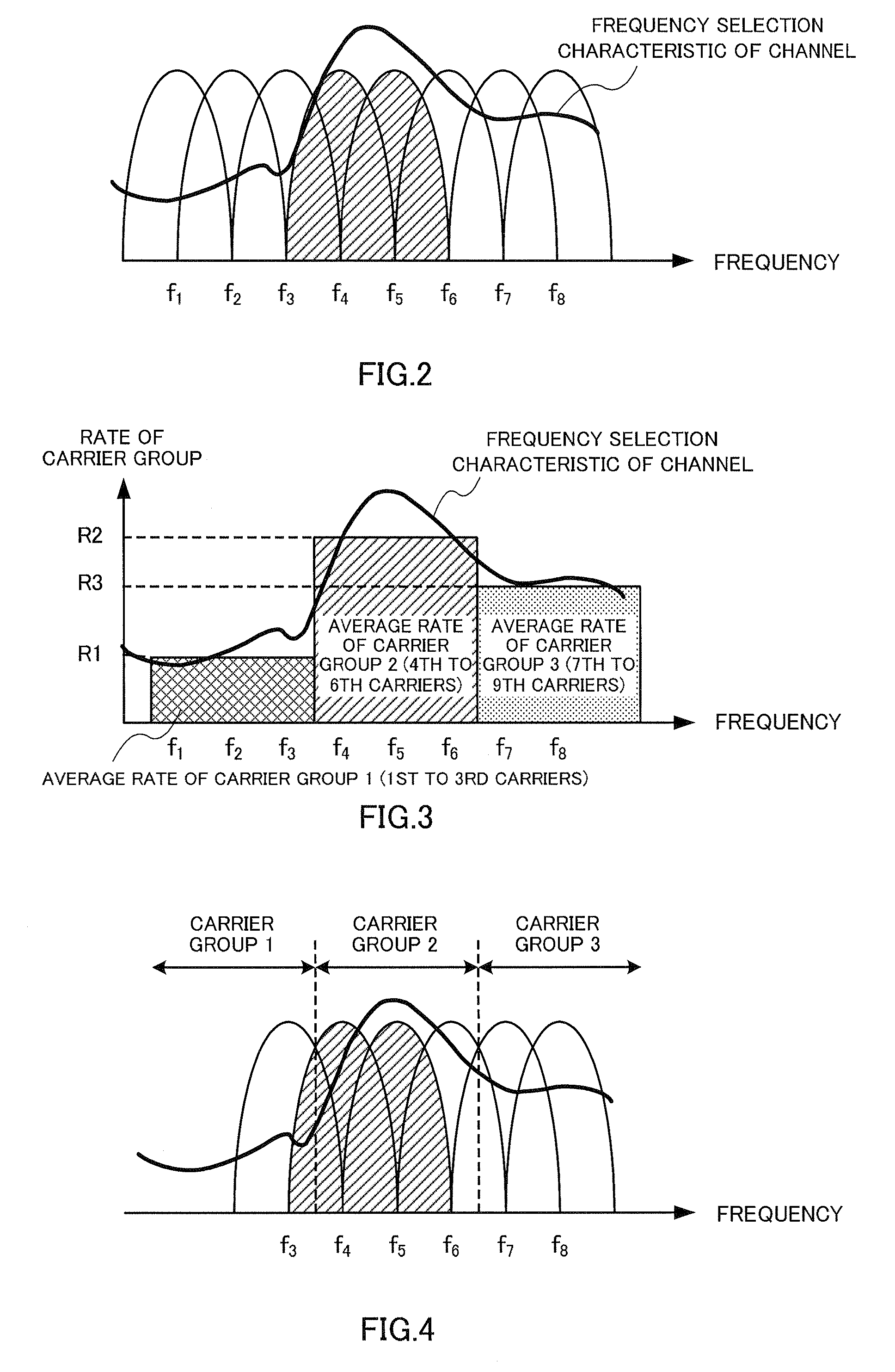
However, with a conventional OFDM system, it is general to adopt an identical transmission rate for all subcarriers and has a problem that differences in transmission performance among the subcarriers due to frequency selective fading are not considered.
If a subcarrier having poor transmission performance adopts the same rate as the subcarriers having good performance, there is a problem that interference resistance performance of the subcarriers is degraded and the transmission efficiency is very low.

Method used


Image

  • Transmitting Apparatus, Receiving Apparatus, Communication System and Communication Method
  • Transmitting Apparatus, Receiving Apparatus, Communication System and Communication Method
  • Transmitting Apparatus, Receiving Apparatus, Communication System and Communication Method

Examples


embodiment

[0032] Puncturing is a method of changing an information transmission rate and efficiency. When, for example, puncturing is performed on a convolutional code having a coding rate of 1 / 2, assume that an output sequence of the convolutional code after interleaving is {A1B1A2B2A3B3 . . . } and that 2 bits are deleted from every 6 bits output. The code then has a coding rate of 3 / 4 and the bit output after the puncturing becomes {A1B1A2B3A4B4A5B6A7B7A8B9 . . . }. However, when 2 bits are deleted from every 4 bits output, the code has a coding rate of 2 / 3 and the bit output after the puncturing becomes {A1B1A2A3B3A4A5B5A6 . . . }. For decoding, when 0 is inserted in a position where puncturing is performed, the decoding method by a code having a coding rate of 1 / 2 can be used as is. Therefore, through puncturing, it is possible to provide flexibility for coding and perform rate matching effectively, thereby enabling easier use. With the present invention, by grouping all subcarriers in a...


PUM


Abstract

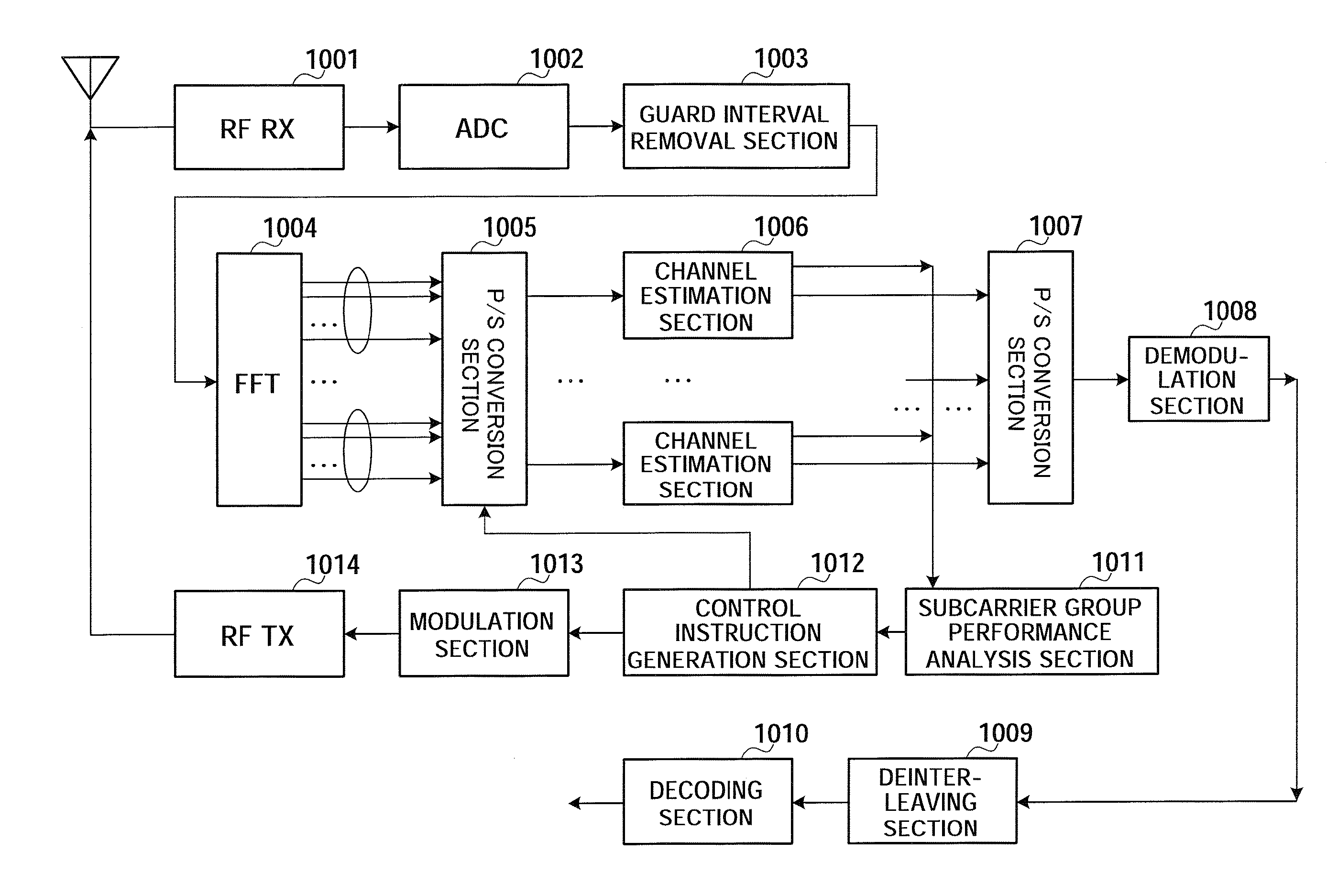
A receiving apparatus that can effectively use spectra to improve the interference resistance and the information transmission efficiency. In this apparatus, a channel estimating part (1006) uses a pilot received from the transmitting end to perform a channel estimation for each of subcarrier groups. A subcarrier group performance analyzer (1011) calculates, based on a channel estimation result, the SIR value of each subcarrier group. A control command generating part (1012) uses the SIR value of each subcarrier group to generate the puncture information and rate of the subcarrier group, then stores the generated puncture information and rate so as to perform an appropriate process when an S / P converting part (1005) performs an S / P conversion for next received information, and then feeds the generated puncture information and rate back to a transmitting apparatus.

Description

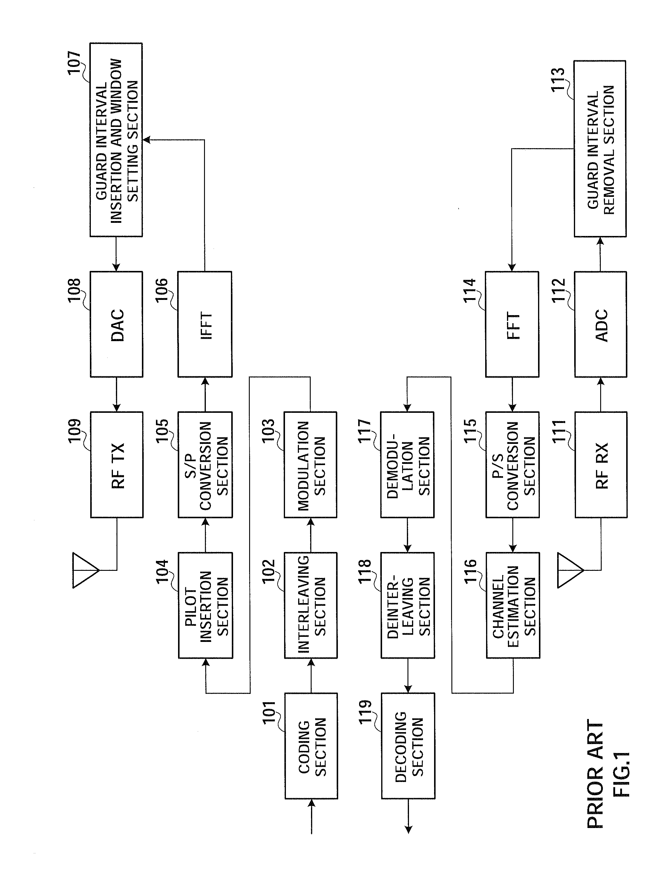
TECHNICAL FIELD [0001] The present invention relates to a transmission apparatus, reception apparatus, communication system and communication method, and, for example, to a transmission apparatus, reception apparatus, communication system and communication method that adaptively control rates of subcarrier groups in a subcarrier communication system. BACKGROUND ART [0002] At present, in mobile communications, with the development of theories and technologies, many new technologies and applications such as orthogonal frequency division multiplexing (OFDM) and MIMO are emerging. These new technologies have an advantage of improving the performance of a mobile communication system substantially and satisfying requirements of radio multimedia and high rate data transmissions. For example, with OFDM, it is possible to improve spectral utilization efficiency by dividing a channel into many subchannels orthogonal to each other in a frequency domain and overlapping carrier spectra of the su...

Claims


Application Information

Patent Timeline
Patent Type & Authority Applications(United States)
IPC IPC(8): H04L27/28H04K1/10
CPCH04B2201/70701H04L1/0002H04L1/0009H04L5/006H04L5/0007H04L5/0046H04L1/0068H04L27/2628H04L27/2646H04L25/0202
Inventor LI, JIFENGYU, XIAOHONG
Owner PANASONIC CORP
Learn More