Method, apparatus and system for self-aligning components, sub-assemblies and assemblies

a technology of self-aligning components and sub-assemblies, applied in the direction of optics, instruments, optical light guides, etc., can solve the problems of disproportionately large percentage of the cost associated with the production of optical communication packages, slow and costly approach, and large obstacle to the production of low-cost telecommunication equipment. achieve the effect of optimizing the energy coupling efficiency

Active Publication Date: 2007-11-15
ALCATEL LUCENT SAS
View PDF13 Cites 55 Cited by
  • Summary
  • Abstract
  • Description
  • Claims
  • Application Information

AI Technical Summary

Problems solved by technology

Currently, a disproportionately large percentage of the cost associated with the production of optical communication packages is taken up with the high precision alignment that is required between micron-sized optical elements within the module such as laser diodes and single-mode fibres.
Due to the high degree of positional accuracy that must be achieved, relatively slow labour intensive techniques are often used for producing such packages.
This slow and costly approach is a major obstacle to the production of low cost telecommunication equipment.
This technique suffers from a large initial investment, long assembly and set-up times. Moreover, the large variety of small volume components typically used to build specialized equipment limits the cost-effective use of this approach.
In addition, this technique relies heavily on known tuning curves which are specific to the customized sub-mount making this technique inflexible in regard to adapting it to different devices.
The major disadvantage of the first two approaches to optical package manufacture described above is one of cost, both being labor and / or capital intensive.
In addition, both of these techniques are limited in their diversity because they both use external manipulation to alter the position of the component.
The MEMS devices also have significant disadvantages associated with them.
The method proposed by Lin et al. suffers from high cost, complexity and reliability issues.
Finally, the MEMS based devices which operate using electrostatic actuation have high voltage requirements and they are typically capable of only small displacements.

Method used


Image

  • Method, apparatus and system for self-aligning components, sub-assemblies and assemblies
  • Method, apparatus and system for self-aligning components, sub-assemblies and assemblies
  • Method, apparatus and system for self-aligning components, sub-assemblies and assemblies

Examples


first embodiment

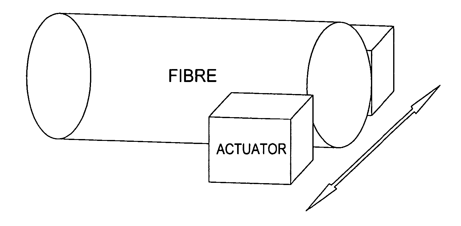
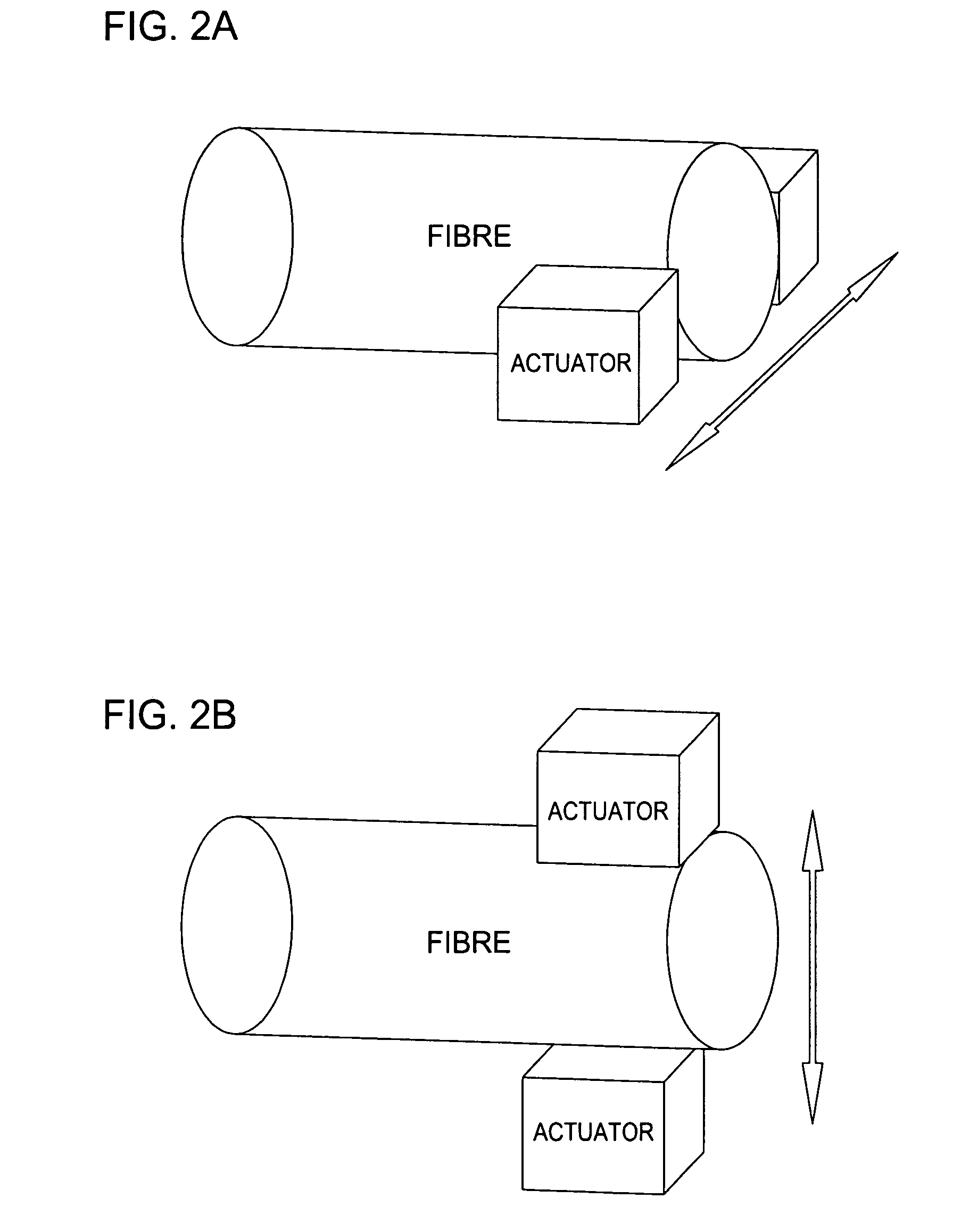
[0029]FIGS. 2-4 depict schematic representations of adjustable component sub-mounts of the invention. Each of these figures depicts a component sub-mount in which a component such as an optical component is physically urged in a particular direction using one or more actuators included within the sub-mount. Thus, a simplified alignment of an optical component within an assembly is realized by controlling one or more actuators included within a-sub mount with the optical component.

[0030]FIG. 2 depicts an adjustable component sub-mount comprising a fiber positioner. Specifically, an optical fiber is physically mounted between two actuators in either a horizontal arrangement (x-axis) per FIG. 2A or vertical arrangement (y-axis) per FIG. 2B. In the arrangement of FIG. 2A, the actuators are used to adapt the position of the optical fiber along the x-axis. Similarly, in the arrangement of FIG. 2B, the actuators are used to adapt the position of the optical fiber along the y-axis. In a fu...

second embodiment

[0033]FIG. 5 depicts a schematic representation of an adjustable component sub mount according to one of the invention. As shown in FIG. 5, the adjustable component sub-mount comprises a laser source sub mount, such as for a laser diode. Specifically, a laser source and adjustable prism are operably positioned via a platform such that light provided by the source passes through the prism.

[0034] The adjustable prism comprises two transparent prism walls (e.g., glass, plastic and the like) denoted as PW1 and PW2 having disposed there between a transparent low modulus material denoted as TLMM and at least one actuator A. In the embodiment of FIG. 5, two actuators denoted as A1 and A2 are shown as being positioned between the transparent prism walls at an upper portion (A1) and a lower portion (A2). All that is necessary is that one or more actuators are operable to perturb the normally coplanar transparent prism walls such that the path of light produced by the source may be controlled...


PUM


Abstract

Method, apparatus and system for self-aligning components, sub-assemblies and / or assemblies wherein actuators are used to physically move the components, sub-assemblies and / or assemblies such that an appropriate alignment is provided. The efficiency of the alignment may be determined with respect to a qualitative measurement (e.g., bit error rate, optical intensity and the like) of an output signal.

Description

FIELD OF THE INVENTION [0001] The present invention relates generally to the assembly of alignment-critical components, sub-assemblies and assemblies and, more particularly, to self-alignment of such components, sub-assemblies and assemblies for directed energy systems such as optical systems. BACKGROUND OF THE INVENTION [0002] Currently, a disproportionately large percentage of the cost associated with the production of optical communication packages is taken up with the high precision alignment that is required between micron-sized optical elements within the module such as laser diodes and single-mode fibres. Due to the high degree of positional accuracy that must be achieved, relatively slow labour intensive techniques are often used for producing such packages. This slow and costly approach is a major obstacle to the production of low cost telecommunication equipment. Alternatives to this approach have been proposed and / or implemented. [0003] One alternative approach provided b...

Claims


Application Information

Patent Timeline
Patent Type & Authority Applications(United States)
IPC IPC(8): G02B6/42
CPCG02B6/32G02B6/3508G02B26/0891G02B6/3588G02B6/4226G02B6/3526G02B6/35
Inventor HUGHES, PATRICK JOSEPHJORDAN, GRACE MARIELYONS, ALAN MICHAEL
Owner ALCATEL LUCENT SAS
Why Eureka
Try Eureka