Image forming apparatus
a technology of image forming apparatus and forming medium, which is applied in the direction of electrographic process apparatus, instruments, optics, etc., can solve the problems of long time spent fixing multi-color toner images onto recording media, and inability to achieve image fixation. , to achieve the effect of convenien
- Summary
- Abstract
- Description
- Claims
- Application Information
AI Technical Summary
Benefits of technology
Problems solved by technology
Method used
Image

Examples
first embodiment
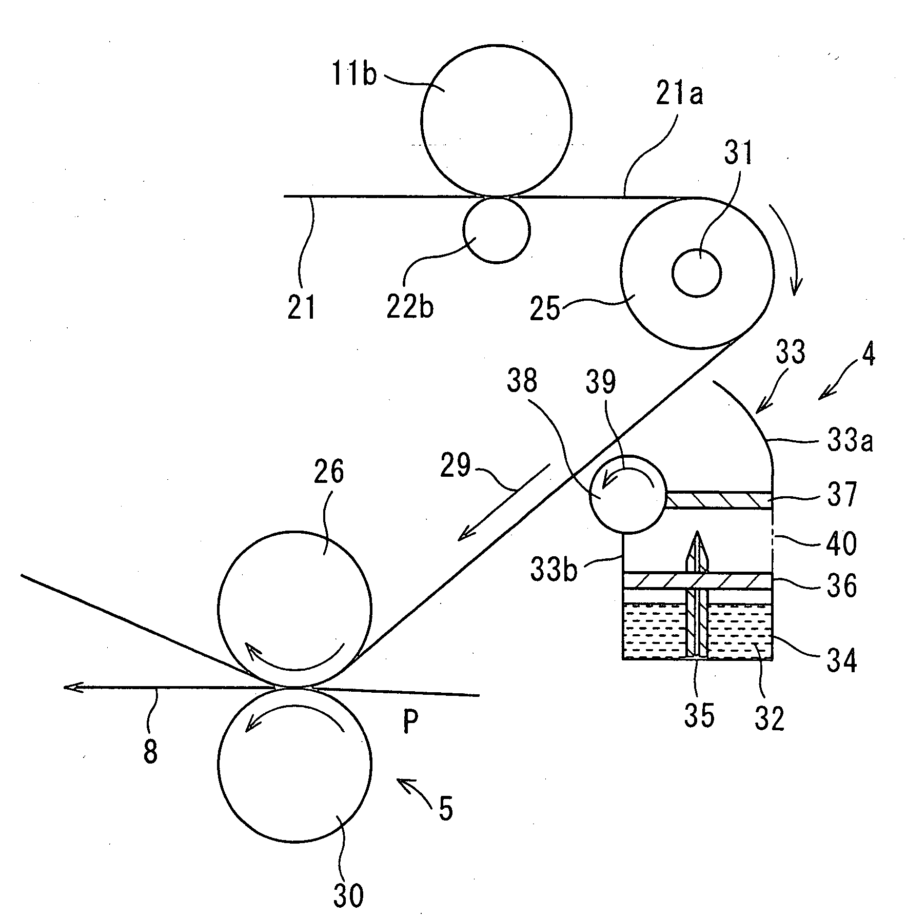
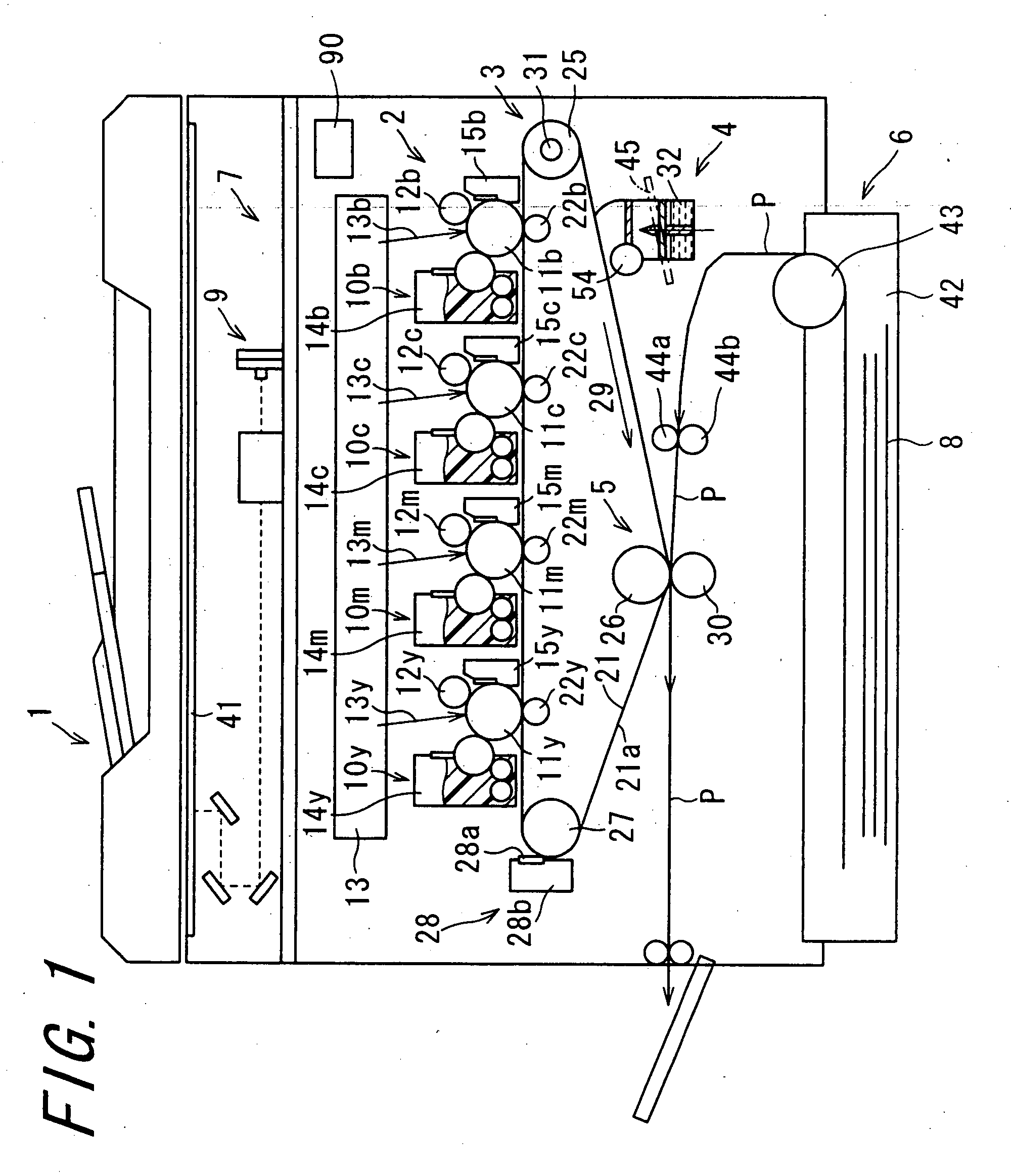
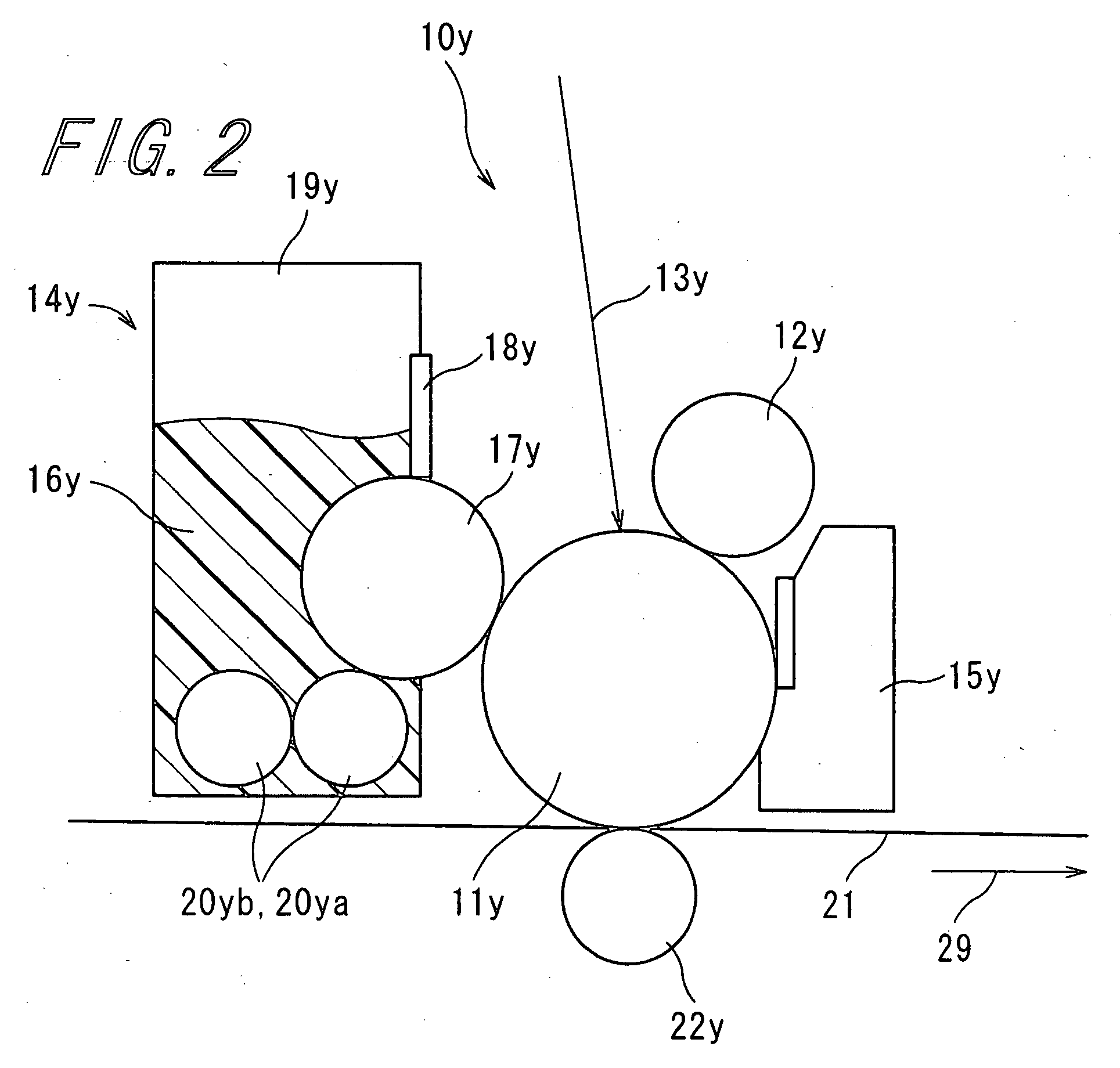
[0057]FIG. 1 is a sectional view schematically showing the constitution of an image forming apparatus 1 according to the invention. FIG. 2 is an enlarged sectional view showing the structure of principal portion (a toner image forming section 2 described later) of the image forming apparatus 1 depicted in FIG. 1. FIG. 3 is an enlarged sectional view showing the structure of principle portion (a fixing fluid applying section 4 described later) of the image forming apparatus 1 depicted in FIG. 1. FIG. 4 is a longitudinal sectional view schematically showing the configuration of the fixing fluid applying section 4. The image forming apparatus 1 is built as a tandem-system electrophotographic image forming apparatus in which toner images of four colors: yellow; magenta; cyan; and black are transferred one after another and overlaid. The image forming apparatus 1 is composed of the toner image forming section 2, an intermediate transfer section 3, the fixing fluid applying section 4, a t...
second embodiment
[0101]FIG. 5 is a sectional view schematically showing the constitution of an image forming apparatus 50 according to the invention. FIG. 6 is an enlarged sectional view showing the structure of principal portion (in specific, a fixing fluid applying section 51 described later) of the image forming apparatus 50 illustrated in FIG. 5. Since the image forming apparatus 50 is similar to the image forming apparatus 1, corresponding portions will be denoted by the same reference numerals, and descriptions thereof will be omitted. The image forming apparatus 50 comprises an intermediate transfer section 3a instead of the intermediate transfer section 3 in the image forming apparatus 1. Moreover, the image forming apparatus 50 comprises a fixing fluid applying section 51 instead of the fixing fluid applying section 4 in the image forming apparatus 1.
[0102]The intermediate transfer section 3a includes a temperature detecting portion 52 as well as the intermediate transfer belt 21, the inter...
third embodiment
[0109]FIG. 7 is a sectional view schematically showing the constitution of an image forming apparatus 61 according to the invention. Since the image forming apparatus 61 is similar to the image forming apparatus 1, corresponding portions will be denoted by the same reference numerals, and descriptions thereof will be omitted. The image forming apparatus 61 comprises an intermediate transfer section 3b instead of the intermediate transfer section 3 in the image forming apparatus 1, and other components thereof are the same as those of the image forming apparatus 1. The intermediate transfer section 3b includes a second heating section 62 as well as the intermediate transfer belt 21, the intermediate transfer rollers 22y, 22m, 22c and 22b, the supporting rollers 25, 26 and 27, and the belt cleaner 28. The second heating section 62 is placed between the supporting roller 25 and the fixing fluid applying section 4 in the direction that the intermediate transfer belt 21 rotates, so as to...
PUM
 Abstract
Description
Claims
Application Information
 - R&D Engineer
- R&D Manager
- IP Professional
- Industry Leading Data Capabilities
- Powerful AI technology
- Patent DNA Extraction
Browse by: Latest US Patents, China's latest patents, Technical Efficacy Thesaurus, Application Domain, Technology Topic.
© 2024 PatSnap. All rights reserved.Legal|Privacy policy|Modern Slavery Act Transparency Statement|Sitemap