Power supply apparatus

a technology of power supply apparatus and power supply device, which is applied in the direction of electric variable regulation, process and machine control, instruments, etc., can solve the problems of reducing the use efficiency of fuel cells, unable to operate the operation of constantly controlling the discharge rate of methanol below a predetermined value, and a large amount of unused methanol discharged, etc., to achieve more inexpensive power supply apparatus

Inactive Publication Date: 2005-04-19
PANASONIC CORP
View PDF9 Cites 182 Cited by
  • Summary
  • Abstract
  • Description
  • Claims
  • Application Information

AI Technical Summary

Benefits of technology

[0022]The “predetermined function” can be easily obtained by measuring the output voltage and the output current at plural measuring points in a range under which the characteristic of its power generating device changes monotonically and acquiring an optimum operating point. The power supply apparatus of the present invention can calculate the operating point by using the predetermined function and can automatically track its operating point constantly onto its desired operating point, even if the operating condition of the generating device varies.
[0025]The operation part calculates the target output voltage or the target output current by using the voltage setting function having the measured current as its parameter, the current setting function having the measured voltage as its parameter, or several measured data. Therefore, the operation part necessitates only a smaller-sized memory in comparison with the case of memorizing a data table of optimum operating points for every operating condition. The present invention has an effect of realizing more inexpensive power supply apparatus.

Problems solved by technology

This decreases the usage efficiency of the fuel cell.
Further, in the case of a fuel cell that uses methanol as fuel, a considerable amount of unused-methanol is discharged.
This raises the problem on the purification method of the discharged methanol.
In the prior art fuel cell, the operation of constantly controlling the discharge rate of methanol below a predetermined value cannot be performed.
Conventionally, in the power generating device in which the output power supplied to the load varies depending on the power generating condition, it has been a problem in this field to provide a power supply apparatus that is constantly operable under a desired operating condition (for example, an operating condition under which amount of the fuel discharged from the fuel cell becomes minimum or the output power of the solar cell becomes maximum).

Method used


Image

  • Power supply apparatus
  • Power supply apparatus
  • Power supply apparatus

Examples


first embodiment

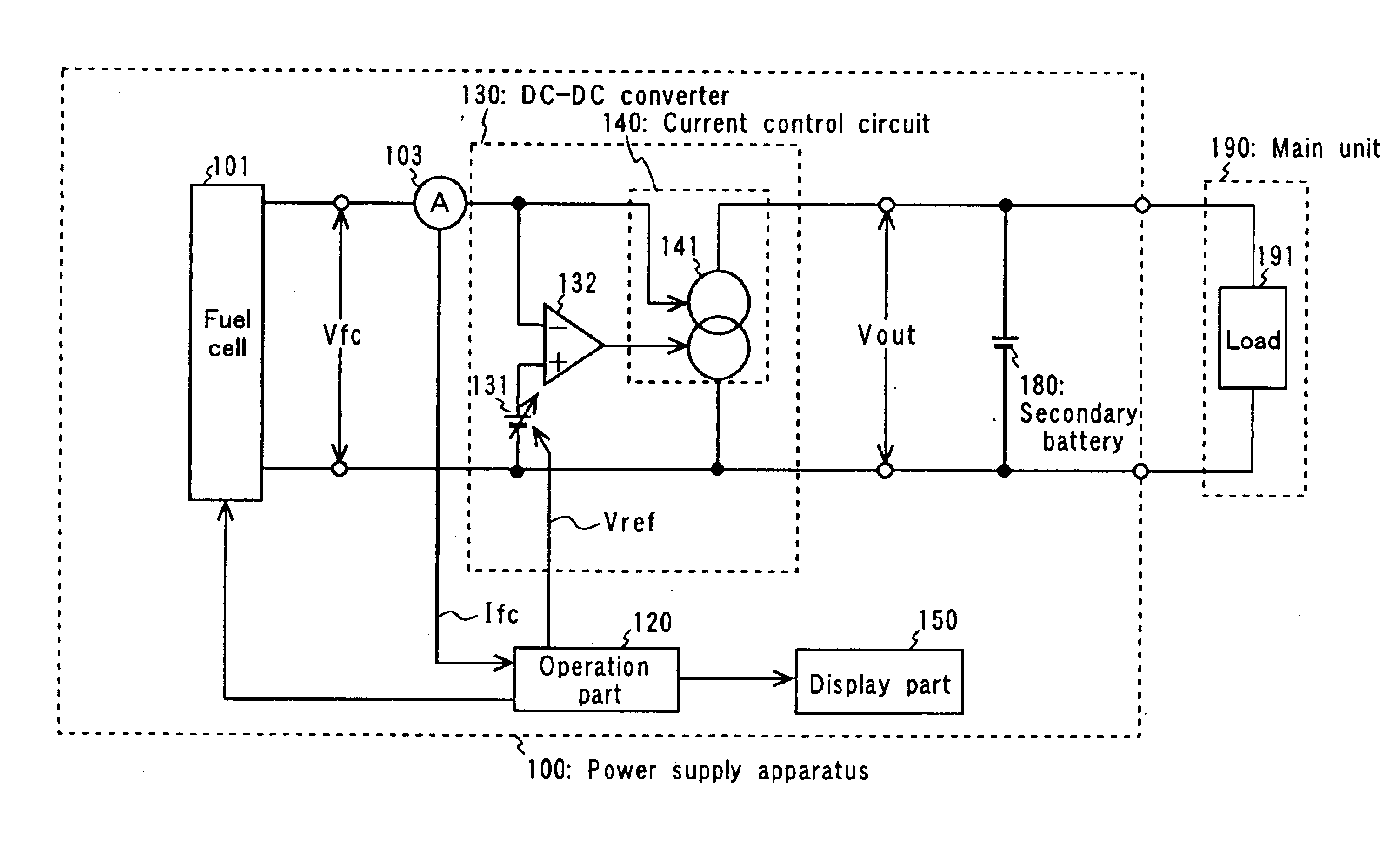
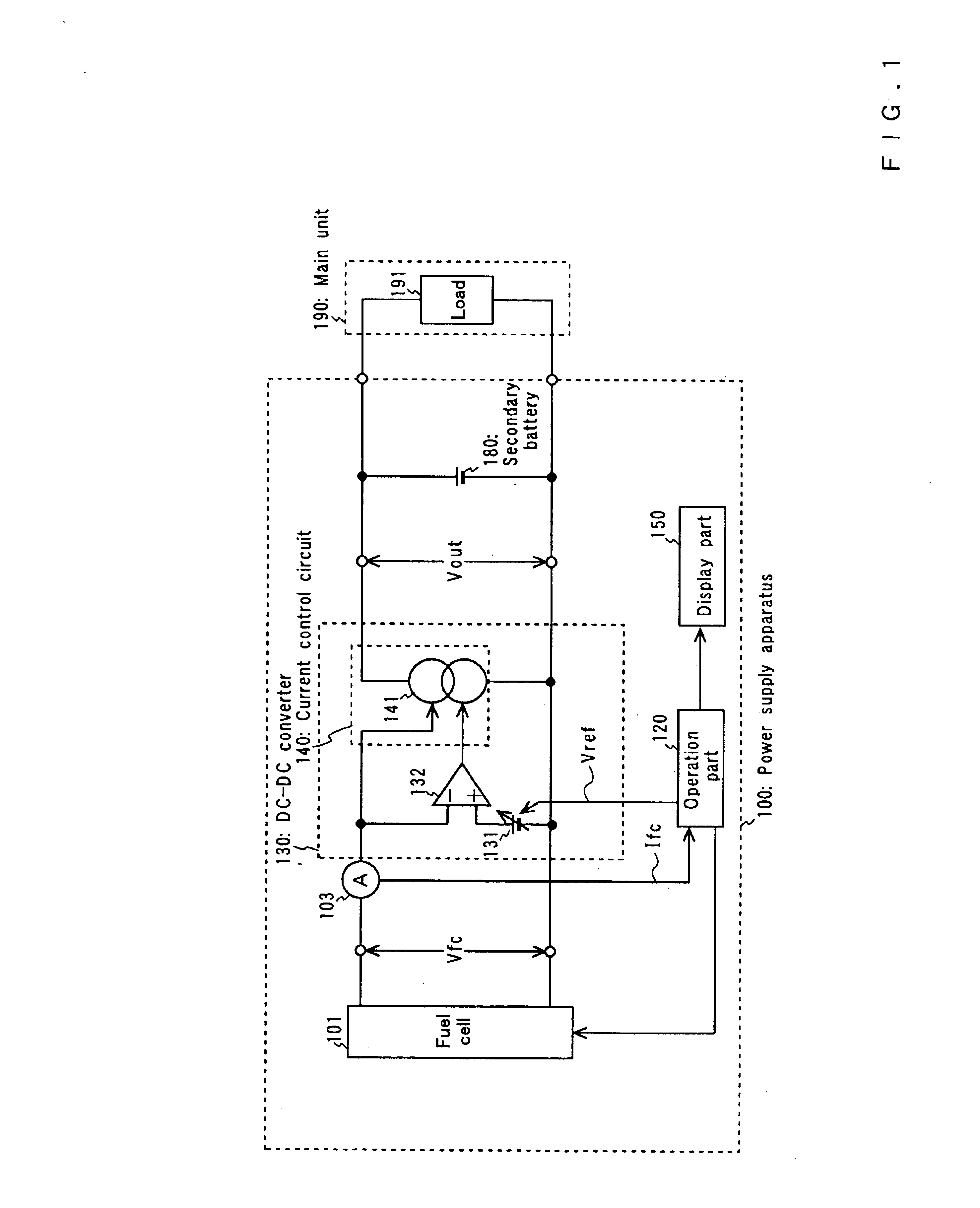
[0035]Referring to FIGS. 1, 2 and 3, a power supply apparatus in accordance with the present invention will be described. FIG. 1 shows a power supply apparatus 100, a secondary battery 180 and a main unit 190. The power supply apparatus 100 has a fuel cell 101, a current detection part 103, an operation part 120, a DC-DC converter 130 and a display part 150. The main unit 190 has a load 191.

[0036]The main unit 190 is a personal computer. The secondary battery 180 is a lithium ion secondary battery. The fuel cell 101 is a balance-type fuel cell using methanol as its material (non-circulation type, a fuel cell of a type that keeps a balance between the amount of used fuel and the amount of output power). The fuel cell 101 receives a constant amount of fuel per unit of time and operates at an operating point at which the output power becomes maximum (output voltage and output current determined uniquely by the fuel feeding rate). In other words, the power supply apparatus 100 in accord...

second embodiment

[0064]Referring to FIGS. 4, 5 and 6, a power supply apparatus in accordance with the present invention will be described below. FIG. 4 shows a power supply apparatus 400, a secondary battery 180 and a main unit 190. The power supply apparatus 400 has a solar cell 401, a voltage detection part 402, a current detection part 403, an operation part 420, a DC-DC converter 430 and a display part 450. The main unit has a load 191.

[0065]The main unit 190 is an automatic measuring device. The secondary cell 180 is a lead storage battery. The solar cell 401 converts light energy into electrical energy directly. The solar cell 401 operates at the operating point at which the output power becomes maximum (output voltage and output current uniquely determined by the amount of light received). That is, the power supply apparatus 400 in accordance with the second embodiment operates in the desired operating condition under which the output power of the solar cell 401 becomes maximum.

[0066]The DC-D...


PUM

PropertyMeasurementUnit
output voltageaaaaaaaaaa
output poweraaaaaaaaaa
currentaaaaaaaaaa

Abstract

A power supply apparatus comprises a power generating device in which the output power supplied to a load varies depending on a power generating condition; a current detection part for detecting the current output from the power generating device; a target output voltage setting part for setting a target output voltage of the power generating device; an error amplifier for amplifying the error between the voltage output from the power generating device and the target output voltage and outputting an error signal; a current control part for receiving input of the error signal, controlling the output current of the generating device so as to make the absolute value of the error signal small and outputting it to external output terminals; and an operation part for calculating the target output voltage as a desired operating condition of the power generating device by a predetermined function having at least the current detected by the current detecting part as an input parameter, and issuing it to the target output voltage setting part.

Description

BACKGROUND OF THE INVENTION[0001]The present invention relates to a power supply apparatus.[0002]The output power of a fuel cell varies mainly depending on the variation in fuel feeding rate. The output power of a solar cell varies mainly depending on the variation in amount of solar radiation. Conventionally, in such a power supply apparatus having a power generating device (cell), the output power of which supplied to a load varies according to the power generating condition, DC output power of the power generating device has been converted into a power of a constant voltage or a constant current by using a DC-DC converter or a DC-AC converter to output it.[0003]A prior art fuel cell apparatus is disclosed in Japanese Patent Laid-Open Publication No. 2000173636. In the prior art fuel cell apparatus, the DC power generated in the fuel cell main body itself is converted into a DC power of a specified voltage by using a DC-DC converter and the converted DC power is constantly supplie...

Claims


Application Information

Patent Timeline
Patent Type & Authority Patents(United States)
IPC IPC(8): G05F1/66G05F1/40G05F1/67G05F1/10G05F1/613H01L31/042H01M8/04H01M8/10H01M16/00H02J7/34
CPCH01M8/04589H01M8/04761H01M8/0488H01M8/0491H01M8/04947H01M16/006H02J7/34H01M8/0494Y02E60/50H02J2001/004H02J2300/30Y02E60/10
Inventor TAKADA, MASAHIROKOZU, KATSUMIICHINOSE, TOSHIHIKO
Owner PANASONIC CORP
Why Eureka
Try Eureka