Fan cover

US20070264119A1Inactive Publication Date: 2007-11-15INVENTEC CORP

Image

  • Fan cover
  • Fan cover
  • Fan cover

Examples


Embodiment Construction

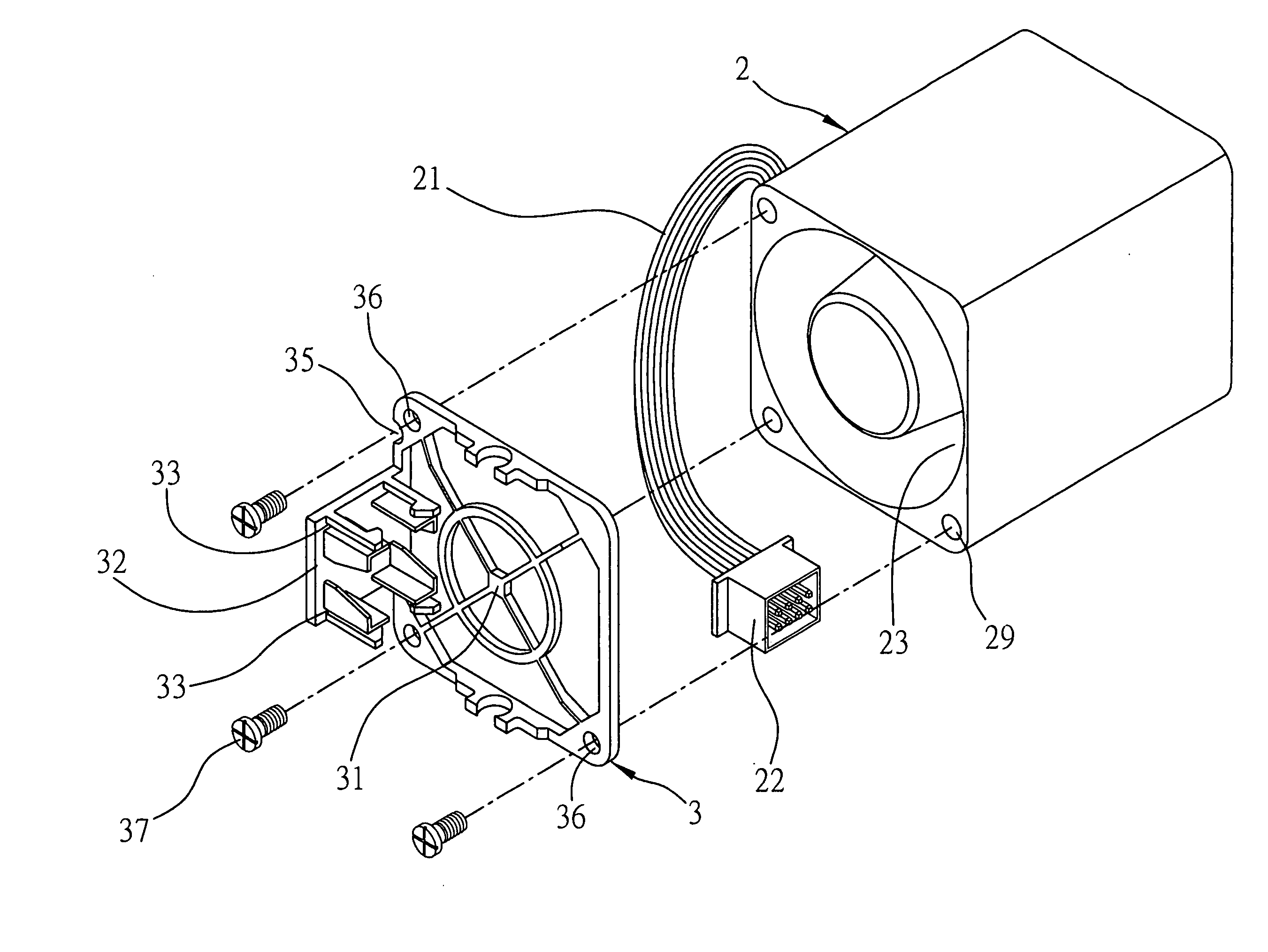
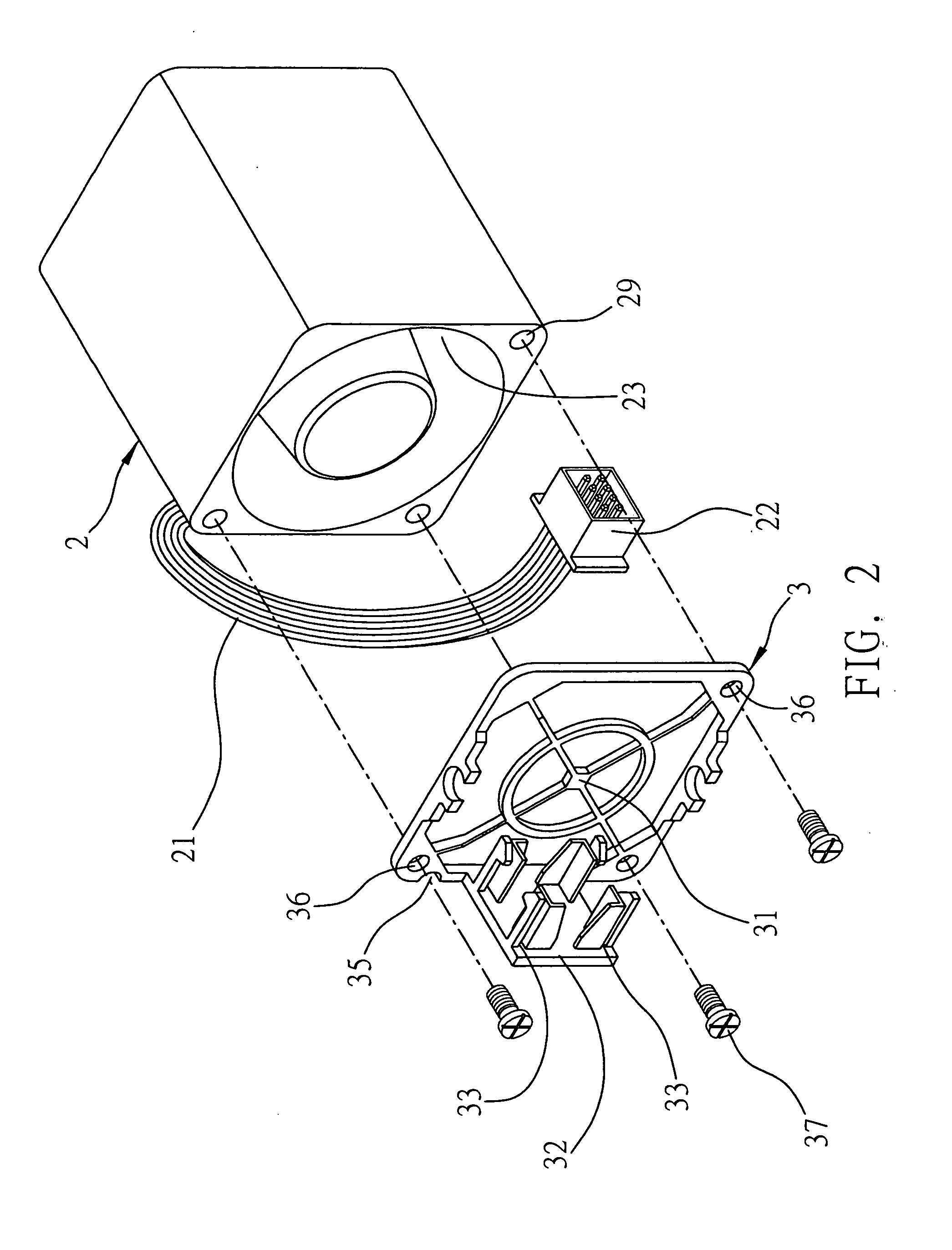
[0022]Please refer to FIG. 2, which is an exploded view of a heat dissipating fan 2 and a fan cover 3 of the preferred embodiment according to the present invention. The heat dissipating fan 2 has a power line 21 and a power line connector 22 connected to one end of the power line 21. The fan cover 3 is used to be integrated with the heat dissipating fan 2. The fan cover 3 comprises a body 31 for combining with and being covered on a side of the heat dissipating fan 2, and a fixing mount 32 disposed in an outside region of the body 31. The fixing mount 32 has two clip units 33 for clipping to the power line connector 22 of the heat dissipating fan 2, allowing the power line connector 22 to be detachably attached to the fixing mount 32.

[0023]According to the preferred embodiment, the fan cover 3 is combined to a side of the heat dissipating fan 2 having an air outlet 23. However, the fan cover 3 can also be combined to another side of the heat dissipating fan 2 having an air inlet.

[0...


PUM


Abstract

A fan cover integrated with a heat dissipating fan having a power line and a power line connector is disclosed. The fan cover includes a body combined with and covered on a side of the heat dissipating fan, and a fixing mount disposed on an outside region of the body. The fixing mount has a clip unit for clipping to the power line connector of the heat dissipating fan, allowing the power line connector to be detachably attached to the fixing mount. Therefore, the heat dissipating fan is detachable form the frame of the server in single step and overcome the drawbacks of the prior art.

Description

BACKGROUND OF THE INVENTION[0001]1. Field of the Invention[0002]The present invention relates to fan cover, and more particularly, to a fan cover which can be detachably attached with a power line connector of a heat dissipating fan.[0003]2. Description of Related Arts[0004]Conventionally, a fan module for heat dissipating in a 1U server has two or three fans, whereas the whole fan module must be detached from the 1U server if one of these fans is malfunctioned, thereby the server must be shut off for taking off the fan module.[0005]Heat dissipating fans can be respectively electrically connected to and detached from a server in recent years. As shown in FIG. 1, a server (not shown) has a fan frame 1 and a patch panel 7 having a plurality of electrical slots 70. The fan frame 1 includes a plurality of accommodation units 10 for a plurality of fans 6 to be accommodated in respectively. The electrical slots 70 are used for electrically connecting to connectors 60 of the fans 6.[0006]H...

Claims


Application Information

Patent Timeline
15 Nov 2007
Publication
US20070264119A1
IPC
F01D25/00
CPC
F04D29/703
Inventors
LIN, LINGER