Device for Ablating Body Tissue
a body tissue and device technology, applied in the field of ablating body tissue, can solve the problems of time-consuming and special surgical skills
- Summary
- Abstract
- Description
- Claims
- Application Information
AI Technical Summary
Benefits of technology
Problems solved by technology
Method used
Image
Examples
first embodiment
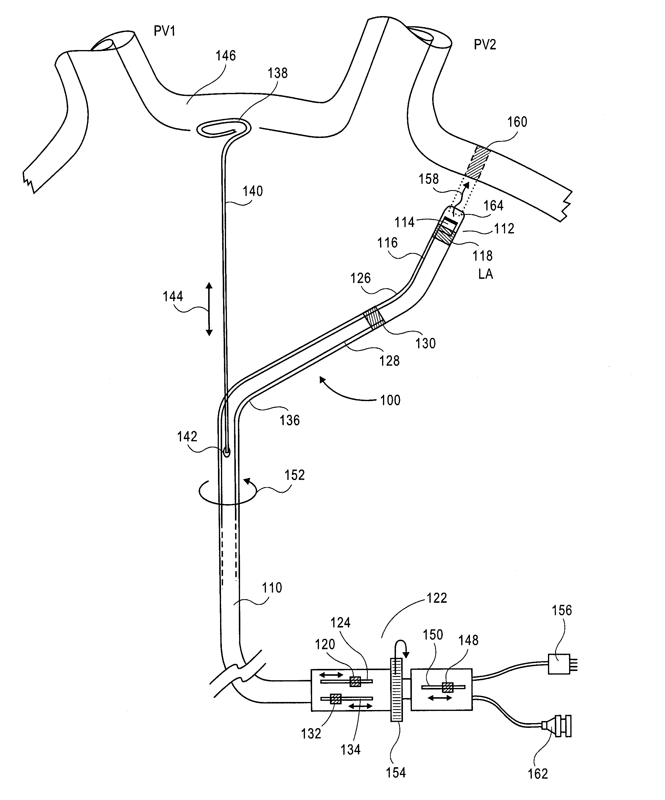
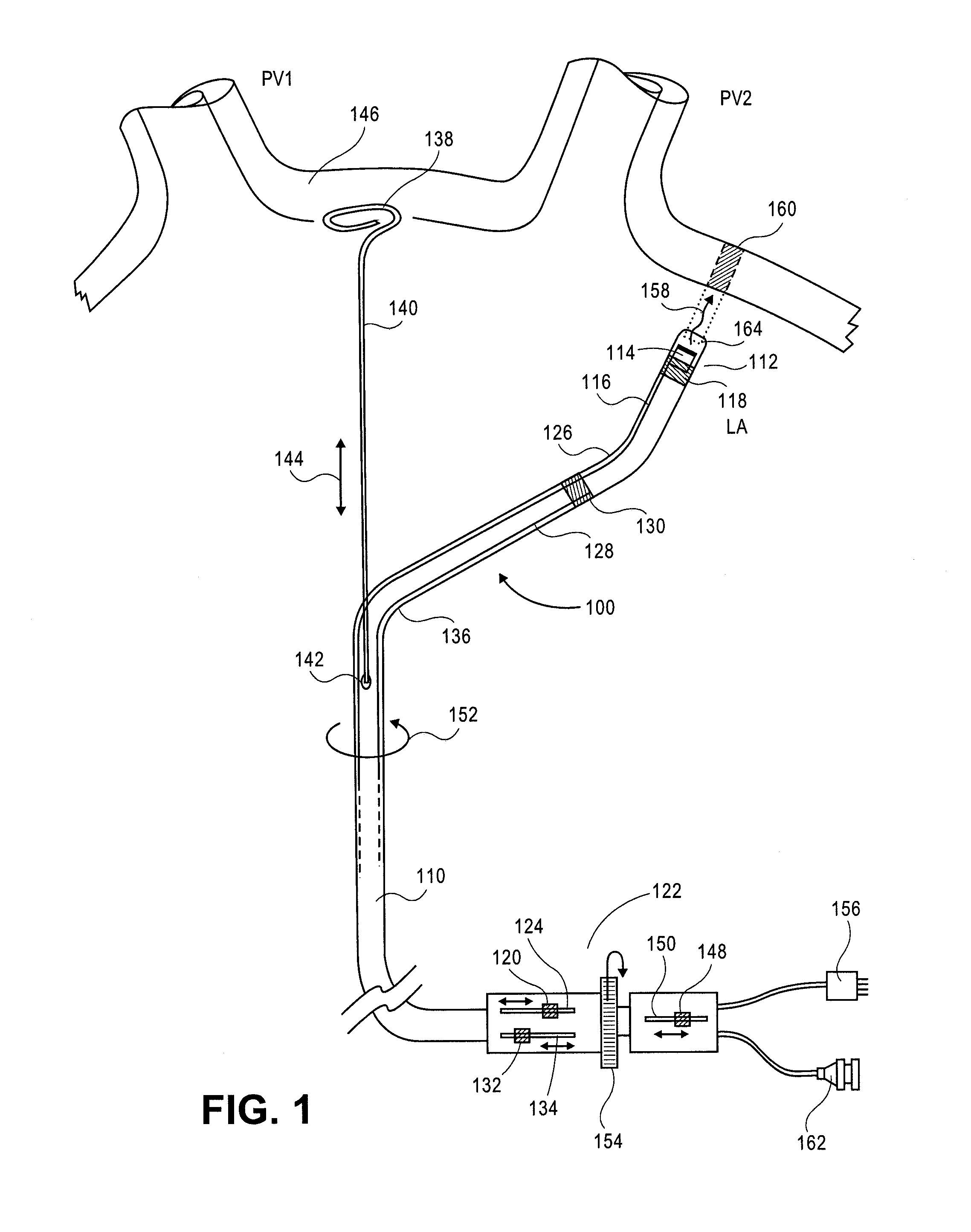
[0076] One aspect of the invention is shown in FIG. 1. As shown, the device 100 includes an elongate member that can be a catheter 110. In other implementations, the elongate member is a cannula, tube or other elongate structure having one or more lumens. The catheter 110 can be made of a flexible multi-lumen tube. As shown, the catheter 110 can include a distal tip assembly 112 positioned at a distal portion of the catheter 110. The tip assembly 112 can house an energy delivery structure, for example, an ultrasound transducer subassembly 114 (described in more detail in reference to FIG. 4).
[0077] Although the ablation device described herein includes a distal tip assembly having an ultrasound transducer as a source of ablation energy, it is envisioned than any of a number of energy sources can be used with various implementations of the invention. Suitable sources of ablation energy include but are not limited to, radio frequency (RF) energy, microwaves, photonic energy, and therm...
third embodiment
[0097] the invention including an alternative distal tip assembly arrangement is shown in FIG. 7. Various details, features and uses of this embodiment include those as described herein regarding other embodiments. In this embodiment an alternative transducer subassembly is provided as shown in detail in FIG. 8. As shown in FIG. 8, the ultrasound transducer 1320 can be mounted on an angled backing 1326. The angle of the backing can range between substantially 0-90°. In one implementation the angle is substantially 10-80°. In another implementation the angle is substantially 30-60°. In another implementation the angle is substantially 40-50°. In a further embodiment the angle is substantially 45°. The transducer can include a shape. In one implementation the transducer is in the shape of an elliptical disc. In another implementation the transducer has a rectangular shape. As shown in FIGS. 7 and 8, in one implementation the transducer 1320 can emit energy in the form of an ultrasound...
fourth embodiment
[0099] the invention including an alternative distal tip assembly arrangement is shown in FIG. 9, and the details of the tip assembly are shown in FIG. 10. Various details, features and uses of this embodiment include those as described herein regarding other embodiments. In this embodiment an alternative transducer subassembly is provided as shown in detail FIG. 10. As shown in FIG. 10, in this implementation, the ultrasound transducer 1420 is mounted at a distal portion of the distal tip assembly 1412. Further, the transducer 1420 is directed substantially toward the proximal direction. As illustrated, in this orientation the transducer 1420 can emit an ultrasound wave 1457 substantially parallel to the longitudinal axis of the distal tip assembly 1412.
[0100] As shown in FIG. 10, proximal to the transducer 1420 an angled reflector device can be mounted. For example, the reflector device can be a cylindrical reflector 1452 with having a face cut at an angle to the distal tip assemb...
PUM
 Abstract
Description
Claims
Application Information
 - R&D
- Intellectual Property
- Life Sciences
- Materials
- Tech Scout
- Unparalleled Data Quality
- Higher Quality Content
- 60% Fewer Hallucinations
Browse by: Latest US Patents, China's latest patents, Technical Efficacy Thesaurus, Application Domain, Technology Topic, Popular Technical Reports.
© 2025 PatSnap. All rights reserved.Legal|Privacy policy|Modern Slavery Act Transparency Statement|Sitemap|About US| Contact US: help@patsnap.com


