Powder fuel engine

a fuel engine and powder technology, applied in the direction of powdered engine fuels, machines/engines, mechanical equipment, etc., can solve the problems of increasing the price of gasoline, forcing consumers to pay a lot more for traffic expense,

Inactive Publication Date: 2007-11-22
LIN YI HSIUNG
View PDF5 Cites 4 Cited by
  • Summary
  • Abstract
  • Description
  • Claims
  • Application Information

AI Technical Summary

Problems solved by technology

But, in recent years, the price of gasoline has been raised more and more, forcing consumers to pay a lot more for traffic expense.

Method used


Image

  • Powder fuel engine
  • Powder fuel engine

Examples


Embodiment Construction

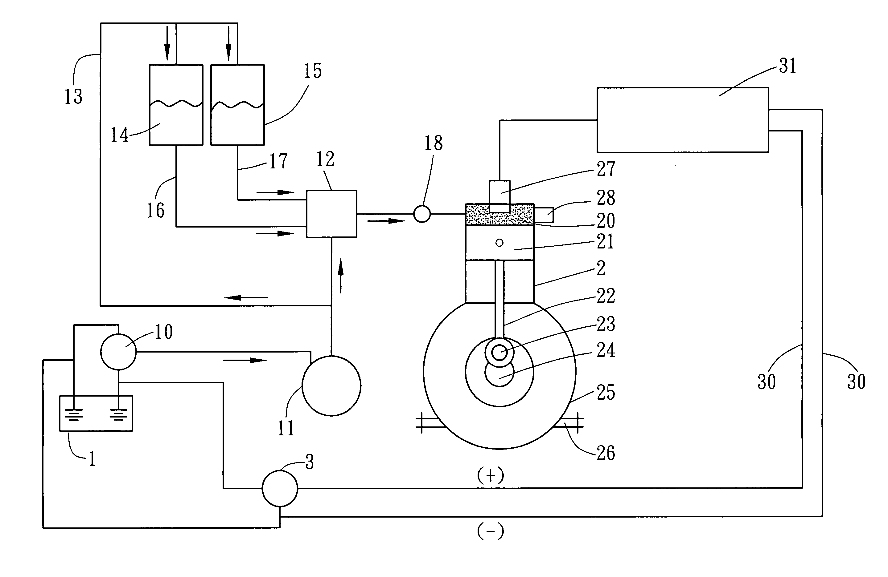
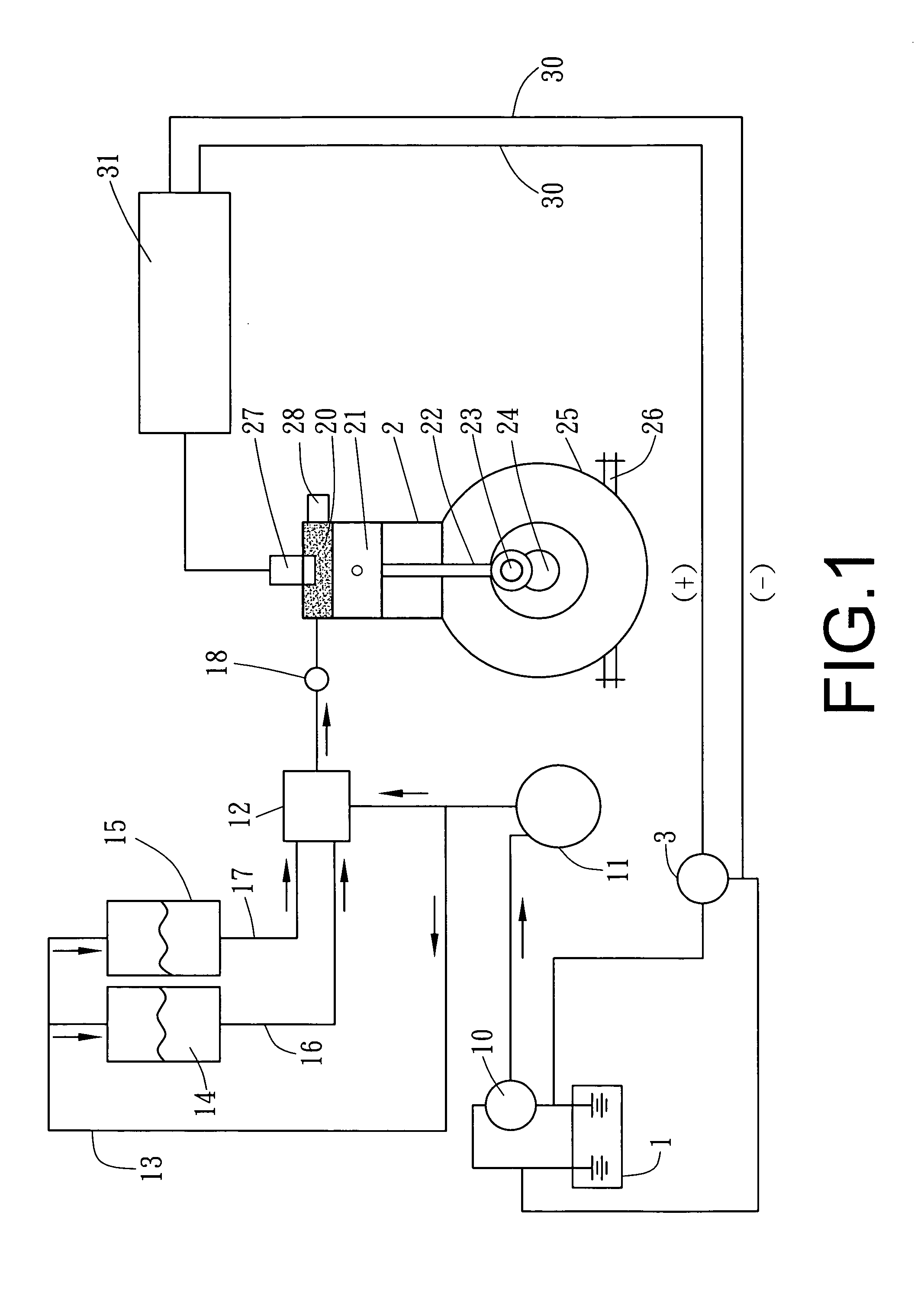
[0009]As shown in FIG. 1, a preferred embodiment of a powder fuel engine in the present invention includes mainly a battery 1, an air compressor 10, a cylinder 2 and a generator 3.

[0010]The battery 1 is connected with the air compressor 10 that is additionally connected with an air tank 11 that is connected with a mixer 12 and two powder tanks 14 and 15 respectively via a pressurization tube 13. Each of the powder tanks 14 and 15 is to store a powder different from each other, and connected with a powder tube 16 or 17 respectively that is connected with the mixer 12 with the other end. A powder jetting device 18 connected beside one side of the mixer 12 is connected with the cylinder 2.

[0011]The cylinder 2 is provided with a powder combustion chamber 20 inside it, a piston 21 installed in the powder combustion chamber 20 and an outlet 28 bored in an upper portion. The piston 21 is connected with a connecting rod 22 that is connected with a shaft 23 by the other end. The shaft 23 is ...


PUM


Abstract

A powder fuel engine includes a battery, a cylinder and a generator. The battery is connected with an air compressor linked with an air tank, and the generator. The air tank is connected with a mixer and two powder tanks respectively via a pressurization tube. The powder tanks are to store different powders and respectively connected with a powder tube connected with the mixer. A powder jetting device connected to the mixer is connected with the cylinder that is provided with a powder combustion chamber, a piston, a spark plug and an outlet. The piston is connected with a connecting rod that is connected with a shaft. The generator is connected with an ignition device that is connected with the spark plug.

Description

BACKGROUND OF THE INVENTION[0001]1. Field of the Invention[0002]This invention relates to a powder fuel engine, particularly to one using two different powders as fuel.[0003]2. Description of the Prior Art[0004]Commonly, a conventional automobile engine requires gasoline mixed with air and combusted in an airtight cylinder, so as to alter chemical energy into mechanical energy for driving itself. But, in recent years, the price of gasoline has been raised more and more, forcing consumers to pay a lot more for traffic expense.SUMMARY OF THE INVENTION[0005]The objective of this invention is to offer a powder fuel engine for an automobile.[0006]The main characteristics of the invention are a battery, a cylinder and a generator. The battery is connected with an air compressor linked with an air tank, and the generator. The air tank is connected with a mixer and two powder tanks respectively via a pressurization tube. The powder tanks are to store different powders and respectively conne...

Claims


Application Information

Patent Timeline
Patent Type & Authority Applications(United States)
IPC IPC(8): F02B45/00
CPCY02T10/34F02B45/02Y02T10/30
Inventor LIN, YI-HSIUNG
Owner LIN YI HSIUNG
Why Eureka
Try Eureka