
Ultrasonic cleaner

a cleaner and ultrasonic technology, applied in the direction of cleaning processes and utensils, cleaning using liquids, chemistry apparatus and processes, etc., can solve the problems of affecting the effectiveness of the cleaning process, damage to the cleaner, etc., and achieve the effect of improving the marketability of inventive cleaners

Inactive Publication Date: 2007-11-22
COLTENE WHALEDENT INC
View PDF7 Cites 20 Cited by
  • Summary
  • Abstract
  • Description
  • Claims
  • Application Information

AI Technical Summary

Benefits of technology

[0015]The benefits of utilizing the solution timer are numerous. Firstly, the cleaner is typically most effective when the solution is fresh and clean. Secondly, periodic changes of the solution minimize the possibility that it would evaporate below the low threshold level over a period of time and, thus, detrimentally affect the effectiveness of the cleaning process and damage the cleaner. Thirdly, the operator of the inventive cleaner does not have to remember and periodically check when the solution was changed or added last which facilitates the operator's job.
[0017]At least one of the benefits of the count-down timer includes facilitating the operator's job. Knowing the remaining time, the operator may attend to other tasks and schedule his time in a manner convenient to him or her.
[0019]The language-selection unit improves the marketability of the inventive cleaner. It also may eliminate the necessity of reconfiguring an ultrasound cleaner when the latter is exported to or purchased in a foreign country speaking in a language different from the country where the cleaner is manufactured.

Problems solved by technology

Secondly, periodic changes of the solution minimize the possibility that it would evaporate below the low threshold level over a period of time and, thus, detrimentally affect the effectiveness of the cleaning process and damage the cleaner.

Method used


Image

  • Ultrasonic cleaner
  • Ultrasonic cleaner
  • Ultrasonic cleaner

Examples


Embodiment Construction

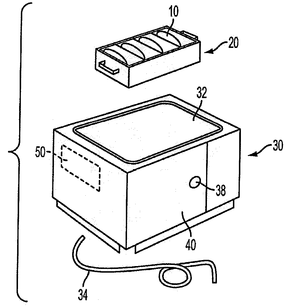
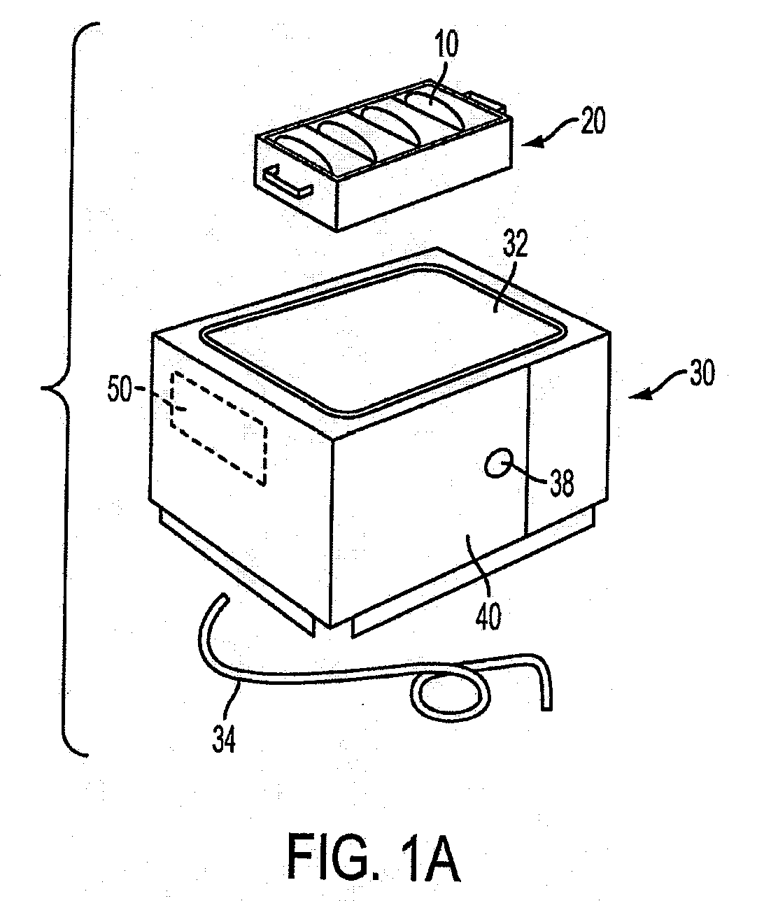
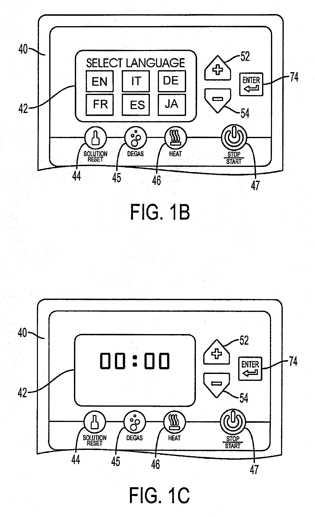
[0028]Referring to FIGS. 1A-1E, there is shown an ultrasonic cleaner 30 configured in accordance with the invention. As shown in FIG. 1A, cleaner 30 is configured with a tank or bath 32 fillable with a cleaning solution and removably receiving a cassette or beaker 20 for storing items 10. The tank 32 has a drain outlet tube 34 and a cover (36 shown in FIG. 5) to sealingly close tank 32 when the latter is in use. The cleaner 30 is provided with a control panel 40 mounted to the exterior surface of the cleaner and defining a user interface that allows the operator to interact with device 30 and set the desired parameters, as disclosed hereinafter. The control panel 40 may be disposed on any exterior surface, part, or attachment of the cleaner 30, as shown in FIG. 5. The cleaner 30 also has an electrical generator (not shown) that puts out a high frequency signal causing one or more transducers (not shown) to rapidly induce compression and rarefaction waves in the cleaning solution in ...


PUM


Abstract

An ultrasonic cleaner is provided with a user interface, display, and a solution timer unit that tracks the amount of time cleaning solution has been in use. The solution life is displayed in hours and minutes that can be adjusted or reset by an operator. The ultrasonic cleaner includes a solution reset key conspicuously located on a control panel that is mounted on a housing of the ultrasonic cleaner. An operator may periodically check how long the solution has been in use by simply looking at a screen displaying the time elapsed since the beginning of the period. The display may also indicate cleaning cycle times and status, such as the completion of a cleaning cycle; and the user interface may allow the operator to set cleaning cycle parameters, such as cleaning cycle time.

Description

CROSS-REFERENCE TO RELATED APPLICATIONS[0001]This application claims the benefit of U.S. Provisional Patent Application 60 / 801,787, filed May 19, 2006, which is incorporated herein by reference.BACKGROUND OF THE INVENTION[0002]1. Field of the Invention[0003]The present invention relates to ultrasonic cleaners operative to clean dental or medical instruments, dentures, optical lenses, eyeglasses, and to a method for operating such cleaners.[0004]2. Prior Art[0005]Professionals in the dental, laboratory and medical fields use ultrasonic systems to clean instruments, apparatus, labware, crowns, dentures and other devices prior to sterilization. Ultrasonic cleaning greatly reduces the risk of cross-contamination and infection that can occur with other types of cleaning. Hence this procedure is critical in protecting instruments and is at the center of infection risk control.[0006]Ultrasonic cleaners use high frequency sound waves propagating in aqueous solutions that create bubbles that...

Claims


Application Information

Patent Timeline
IPC IPC(8): B08B3/12B08B3/00B08B7/04
CPCB08B3/12
Inventor SULLIVAN, JERRY
Owner COLTENE WHALEDENT INC
Learn More