Hole punch element

a technology of punching element and support structure, which is applied in the direction of digitally marking record carriers, digitally marking instruments, and punching by punching, etc., can solve the problems of paper jamming in the punching device, and the force needed to compress the die spring directly adds to the hand or operating force required to cut the hole, so as to reduce the punching effort, minimize the return spring force, and lighten the spring force

Active Publication Date: 2007-11-22
WORKTOOLS
View PDF29 Cites 7 Cited by
  • Summary
  • Abstract
  • Description
  • Claims
  • Application Information

AI Technical Summary

Benefits of technology

[0011] To further improve the efficiency of a hole punch, the pull out force of the pin must be reduced. One way to reduce the force is to make the hole in the paper larger than the pin diameter. A non-circular inner circumference can make it easier to expand the hole about a circular pin. For example, an oval hole in a sheet with its largest diameter sized greater than the punch pin diameter would allow the punch pin to pull out easily. To create an oval hole with a circular pin, in one embodiment, the base or anvil of the frame should be substantially uneven or angled. The paper flexes out of a flat plane at the anvil. The pin thereby presses the paper at a substantial angle off perpendicular to the punch pin creating a slightly ovoid hole. With such an arrangement, the smaller diameter of the ovoid hole remains equal or smaller than the pin diameter, while the larger diameter of the ovoid hole is larger than the pin diameter. The pin can easily force open the narrow direction of the hole when the paper is repositioned perpendicular to the pin since the loose fitting larger diameter direction can flex toward the pin. The ovoid hole becomes slightly distorted into a round shape that is larger than the simple round hole that is ordinarily made by the pin.
[0014] An approach to reduce punching effort is to minimize the return spring force. A return spring is commonly used to return the actuation handle back to the start position and to withdraw the punch pin from the punched hole in the sheet material. A first way to achieve a lighter spring force is to reduce the pull out force described above. A lighter spring provides a particular advantage in light duty use, but is also advantageous in any type of punching application. A second way to reduce return spring force is a simplified linkage that enables a user to directly pull out a pin from a punched hole. The return spring may then be just strong enough to retract the pin in most circumstances; the return spring need not be so strong that it can retract the pin under the worst case. Examples of such worst cases include when punching through a very thick stack of papers when the papers have some glue or other contamination, or when the pin has become dull and draws more paper edge into the hole. In such worst case instances, the user can augment the return spring power by pulling up upon an operating handle to retract the pin. Accordingly the spring force may be substantially reduced.

Problems solved by technology

When the pin does not retract in this type of design, the paper becomes jammed in the punching device since there is no further way to force the pin out.
Also, the force needed to compress the die spring directly adds to the hand or operating force required to cut the hole.

Method used


Image

  • Hole punch element
  • Hole punch element
  • Hole punch element

Examples


Embodiment Construction

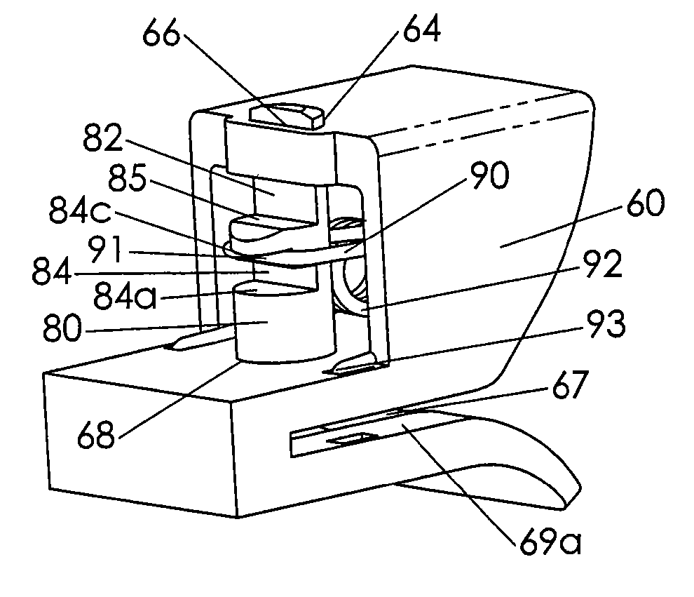
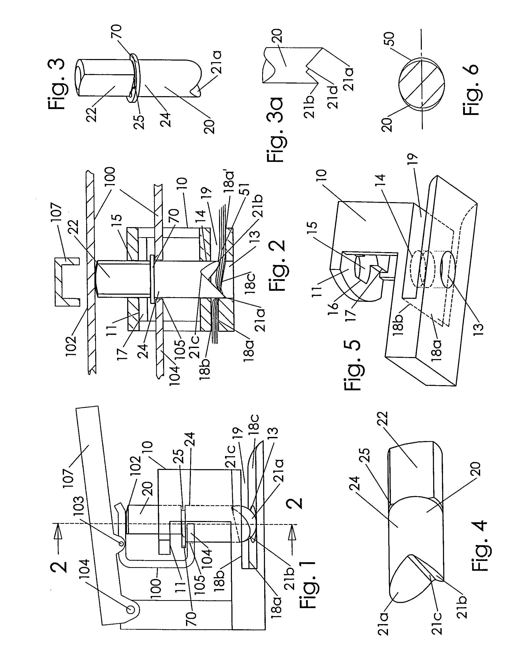
[0034] The present invention is directed to a hole punch element. A hole punch element may be defined as the punch pin, or as the structure within the immediate region of the hole punch device near the pin including the structures that guide the pin and the sheet media or substrate to be punched, such as a stack of papers. For example, a die cast punch support structure may guide pins as well as support an operating handle.

[0035] FIGS. 1 to 7 show one exemplary embodiment of an improved punch element. Pin 20 is vertically slidable and guided in frame 10 along a longitudinal pin axis, depicted as a vertical, dashed line. In FIG. 1, pin 20 is shown in an intermediate position between an uppermost position and a lowermost position. Lower cutting point 21a of pin 20 is just protruding into anvil cavity 13. Upper cutting point 21b of pin 20 has not entered cavity 13 in FIG. 1.

[0036] Tie bar 100 is linked to pin 20. Tie bar 100 is preferably a side facing “U” channel in the illustrated ...


PUM

PropertyMeasurementUnit
angleaaaaaaaaaa
angleaaaaaaaaaa
slope angleaaaaaaaaaa

Abstract

A hole punch device that reduces the force required to create a hole in papers or other sheet media. A punch element of the hole punch device includes a locally sloped or indented floor to create a bend in the sheet media as it is punched to create an enlarged, oval hole. The punch pin may include an expanding sleeve surround the pin that forms a larger diameter during the cutting stroke and springs back to a smaller diameter during a pull out stroke. A coiled torsion return spring is positioned remotely from and non-coaxially with the punch pin. A keyed pin and support frame arrangement ensures a predetermined rotational orientation of the pin for sequential cutting for reduced cutting force. A long lead-in surface in the frame helps installing sheet media into the feed slot of the punch element.

Description

CROSS-REFERENCE TO RELATED APPLICATIONS [0001] This application is a continuation application of co-pending U.S. application Ser. No. 11 / 215,423, filed Aug. 30, 2005, whose entire contents are hereby incorporated by reference.FIELD OF THE INVENTION [0002] The present invention relates to hole punching devices used to cut holes in sheet material. More precisely, the present invention relates to a punch pin and support structure. BACKGROUND OF THE INVENTION [0003] A paper punch is a common device found in offices and schools. It is used to cut holes in paper under finger or hand pressure. Typically, a paper punch element includes a pin, and a frame to support the pin over a paper slot. The pin moves axially, or vertically, into the papers. It is desirable to minimize the force required to cut a hole into a stack of papers since these tools are usually operated under hand or finger pressure. To be sure, even a motorized paper punching device benefits from reduced force since a smaller ...

Claims


Application Information

Patent Timeline
Patent Type & Authority Applications(United States)
IPC IPC(8): G06K1/02
CPCB26F1/14B26D5/10Y10T83/9476Y10T83/885Y10T83/9437Y10T83/9435Y10T83/9428Y10T83/9423Y10T83/8828
Inventor MARKS, JOEL S.
Owner WORKTOOLS
Why Eureka
Try Eureka