
Apparatus for monitoring and regulating soil moisture

a technology of soil moisture and apparatus, applied in the field of apparatus for monitoring soil moisture, can solve the problems of owner neglecting this task, tedious and time-consuming constant monitoring of soil condition of plants, and affecting the growth of plants, so as to reduce tedium and guesswork, improve the effect of soil moisture, and simplify and low-cost construction

Inactive Publication Date: 2007-11-22
SARGENT RONALD J
View PDF11 Cites 23 Cited by
  • Summary
  • Abstract
  • Description
  • Claims
  • Application Information

AI Technical Summary

Benefits of technology

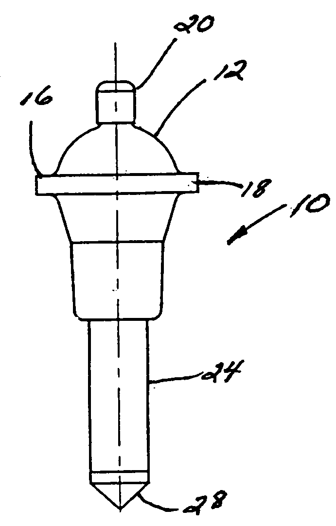
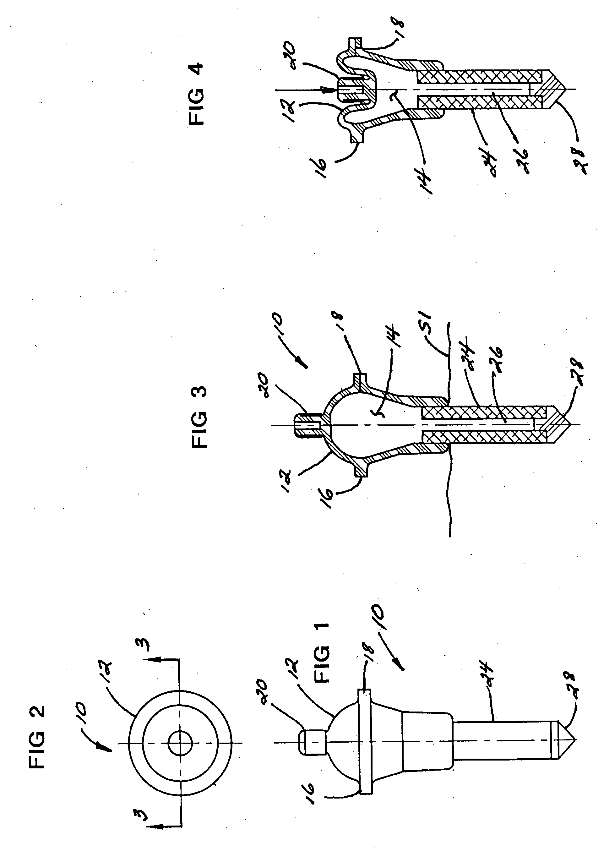
[0017]The tubular housing may be transparent so that the water supply can be conveniently monitored. One or more supporting spikes or stakes may be carried by the housing to mount the apparatus in the soil with the sensor inserting into the soil.
[0025]It is a further object of this invention to provide an apparatus for monitoring soil moisture that significantly reduces the time, tedium and guesswork normally associated with monitoring the water needs of a plant.

Problems solved by technology

Applying too little or too much water may interfere with the growth of the plant or even kill the plant.
Constantly monitoring the soil condition of the plant is usually tedious, time consuming and annoying.
Oftentimes, the plant owner neglects this task and, as a result, plants suffer from lack of water.
On the other hand, an inattentive plant owner may inadvertently over water the plant, which can be just as damaging.
Even if the soil condition of the plant is properly monitored, it can be often difficult to accurately judge precisely how much watering is required.
This results in guesswork which can lead to either underwatering or over watering and the harmful consequences described above.
Even if performed at proper intervals, hand-watering plants can be tedious and time consuming.
Although many types of automatic watering systems are known, these tend to be fairly complicated and expensive.
Many are only suitable for outdoor or green house use or for use with large numbers of plants.
Most conventional automatic watering systems are not appropriate for use with potted plants or a small number of plants.
As additional problem with conventional automatic watering systems is that many of these devices are time dependent and a plant's need for water is often not solely a function of time.
This apparatus employs a fairly complicated construction with a number of small parts including a flexible diaphragm, a coil spring and a protruding check valve.
The numerous parts and relatively high cost of manufacturing this item renders it commercially impracticable.
However, typically these devices provide for only a single watering.
This is time consuming and inconvenient.

Method used


Image

  • Apparatus for monitoring and regulating soil moisture
  • Apparatus for monitoring and regulating soil moisture
  • Apparatus for monitoring and regulating soil moisture

Examples


embodiment 80

[0081]Referring now to FIGS. 13 to 17 and 13A and 13B, another embodiment of the invention which both monitors soil moisture level and limitedly waters the soil S3 shown at numeral 80. In this embodiment 80, an elongated tubular chamber 82 supports an upper cap 84 having a funnel 86 disposed at the upper end of the tubular chamber 82. Chamber 82 is preferably transparent so that the buoyant sealing ball 98 is viewable therethrough.

[0082]A funnel-shaped cap 84 is formed of opaque material and includes a funnel 86 for filling the chamber 82 through the base opening 106 which includes obstruction means for preventing the sealing ball 98 from floating up and out of the apparatus.

[0083]A stake 88 carrying a porous sensor 70 as previously described is connected to the lower end of the chamber 82 and includes an air passageway 94 from cavity 92, the upper end of passageway 94 being sealed by sealing ball 98 when in the downward position shown in solid in the drawings. The cycle of this app...

embodiment 110

[0090]Gradually, the plant dissipates the available water from the soil S4 and the soil dries sufficiently such that it pulls the water from the pores of sensor 70. This unplugs the pores and allows air to enter chamber region 180 in the direction of arrow A. The partial vacuum within the chamber 130 is broken and, as a result, water is dispensed from the apparatus 110 through dispensing outlet 124 in the direction of arrow C into soil S4 and the water level within chamber 130 gradually drops. Eventually, the weight of float 152 causes a break of magnetic contact with upper support 114 and the float 152 drops within housing 112 until the lower end of the float 152 approaches lower support member 116. Lower magnets 170 and 172 eventually attract one another and the float 152 is pulled by snap action into engagement with the lower support member 116. This urges the ball valve 132 to open so that low pressure water is again introduced into the chamber 130. The water level rises and the...

embodiment 190

[0097]Referring now to FIG. 32, an alternate embodiment of the invention previously described in FIGS. 26 to 31 is there shown generally at numeral 190′. This embodiment 190′ is substantially identical to embodiment 190 except that a screw cap 202′ is provided in lieu of the resilient plug 202 previously described. This embodiment 190′ is shown embedded within soil S6 within a planting pot R adjacent the plant P to be watered.

[0098]Referring lastly to FIG. 33, another embodiment of the invention is there shown generally at numeral 220 which incorporates a siphon overflow surge tank 230 coupled to and positioned below a main water chamber 222. After the main chamber 222 has been filled with water at 226 through the sealable opening 224 and the soil S6 within planter T has become sufficiently moist so as to plug the flow of air through the sensor 70 of the soil spike 250 as previously described, the water 234 contained within the siphon tank 230 is there held without leakage or distri...


PUM


Abstract

A water moisture sensing and watering apparatus including a housing having a water chamber that is at least partially evacuatable. A porous sensor is communicably connected to the chamber. When the moisture in the soil is sufficiently high, the pores of the sensor filled sufficiently to become plugged so that a vacuum or low-pressure region and water are maintained within the chamber. When the moisture of the soil drops below a predetermined level, the moisture in the pores is pulled out by the soil and plant roots sufficiently for air to be transmitted through the pores of the sensor into the chamber, increasing pressure in the chamber and providing an indication that water is needed in the soil and, in certain embodiments, automatic watering the soil and plant roots.

Description

CROSS-REFERENCE TO RELATED APPLICATIONS[0001]Not applicableSTATEMENT REGARDING FEDERALLY SPONSORED RESEARCH OR DEVELOPMENT[0002]Not applicableINCORPORATION-BY-REFERENCE OF MATERIAL SUBMITTED ON A COMPACT DISC[0003]Not applicableBACKGROUND OF THE INVENTION[0004]1. Field of the Invention[0005]This invention relates generally to an apparatus for monitoring soil moisture and, more particularly, to an apparatus for sensing when the soil supporting a plant requires watering and for automatically watering the plant when a sufficient lack of moisture is detected.[0006]2. Description of Related Art[0007]Virtually all plants require periodic watering. Providing the soil that supports a plant with the proper amount of water is very important. Applying too little or too much water may interfere with the growth of the plant or even kill the plant. Constantly monitoring the soil condition of the plant is usually tedious, time consuming and annoying. Oftentimes, the plant owner neglects this task ...

Claims


Application Information

Patent Timeline
Patent Type & Authority Applications(United States)
IPC IPC(8): B05B12/08A01G27/00
CPCA01G27/006A01G27/003
Inventor SARGENT, RONALD J.
Owner SARGENT RONALD J
Learn More