
Deflectable variable radius catheters

Inactive Publication Date: 2007-11-22
NGUYEN DUY +3
View PDF31 Cites 214 Cited by
  • Summary
  • Abstract
  • Description
  • Claims
  • Application Information

AI Technical Summary

Benefits of technology

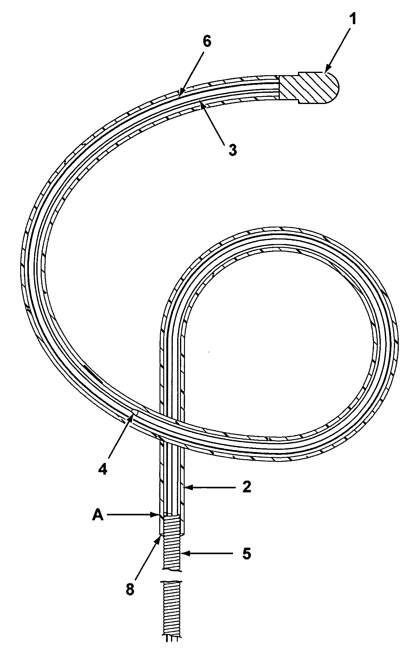
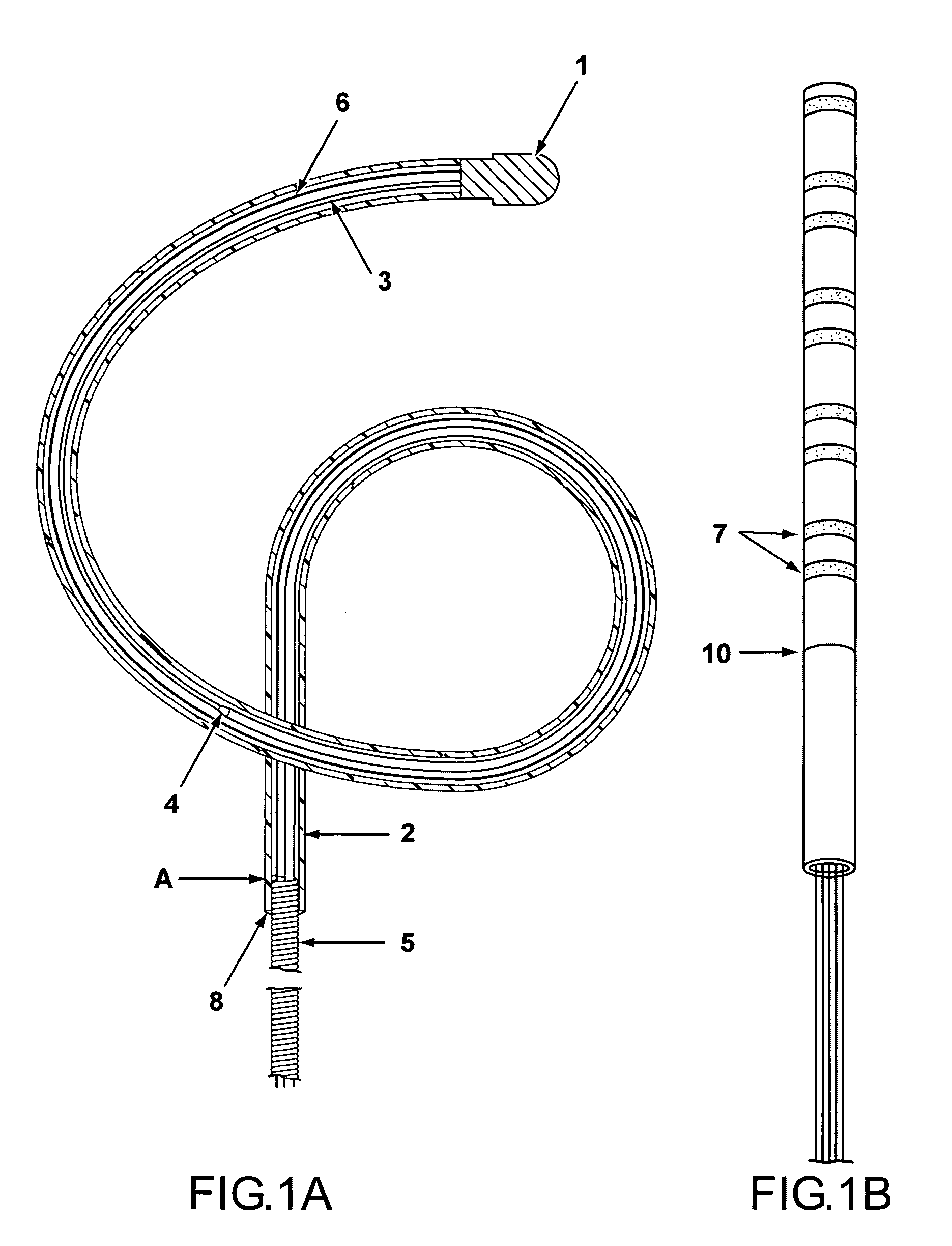
[0006] It is desirable to be able to direct catheter tips or distal sections of catheters in a variety of directions to accommodate numerous surgical procedures and anatomical features. In one aspect, the invention provides a deflectable catheter capable of forming one of many variable radius, spiral forms from a flexible distal end section. In one embodiment, the catheter employs a variable radius control wire to extend, contract, or deform a pre-formed loop structure, as a loop structure is typically produced from conventional, bidirectional deflectable catheter. The extended loop can essentially create a three dimensional, spiral-like form or geometry. The loop can also form a partial or complete circle. The ability of a single catheter to create the multitude of shapes and sizes possible allows a user to access a greater number of anatomical areas without changing the catheter or the size of the distal end during a procedure or treatment.
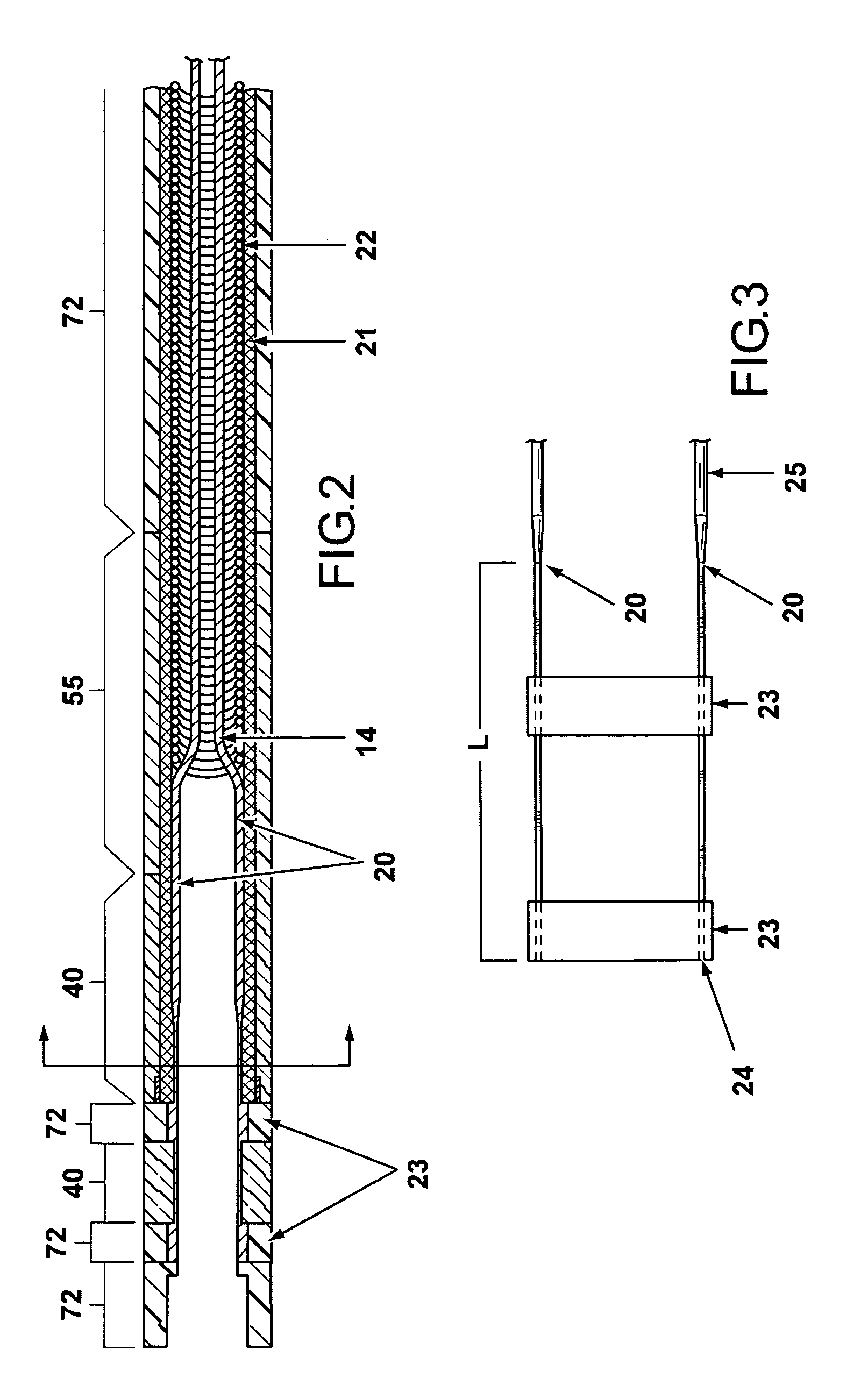
[0009] Various alternatives and specific embodiments of this general catheter are possible. For example, the catheter can further comprise a shape wire at the distal section, where the shape wire is preferably a Nitinol composition. The radius control wire can be connected to the distal end and the distal end can comprise a tip electrode. The catheter distal section can be composed of a variety of external, biocompatible coatings or coverings as known in the art, including a flexible polyether block amide, such as one of the many Pebax polymers available. More than one polymer composition can be used along the length of the distal section and at least two polymer compositions can have different hardness properties on the durometer A scale. When two bidirectional control wires and one variable radius control wire are used, the bidirectional control wires and the variable radius control wire can be housed separately within separate compression coils. The variable radius control wire is in a separate compression coil to avoid unintended left to right movement of the distal tip section of the kind preferably controlled by the bidirectional control wires when engaging the variable radius control wire to adjust the loop at the distal end. In a preferred embodiment, additional control of the desired loop form or spiral form can be achieved by using a flattened wire portion of the variable radius control wire, such that, for example, the most distal end and the end connecting to the tip or near the tip is a flattened wire. The use of flattened wire sections enables increased control over the loop.
[0011] In another general aspect, the invention provides a deflectable catheter comprising a flexible distal end section, having a distal tip and optionally a tip electrode, and having a proximal end with two or more actuators for controlling the shape of the distal end section. A first control wire, and optionally more than one control wire, is connected to a desired deflection point at or near the end of a straight portion of the central shaft region, and a variable radius control wire is connected at or near the distal tip or tip electrode. As commonly known, the catheter can include a central shaft region that connects the distal end section to a handle and actuator at the proximal end. The shaft includes connections or continuing wire lengths so that a first, and optional additional control wire and the variable radius control wire can be operably attached to the actuators at the proximal end for the user to engage the wires. One of the actuators at the proximal end can engage a first control wire to produce a left to right motion at the end of the straight portion of the central shaft region. Then, another actuator at the proximal end that engages the variable radius control wire can reduce or extend the radius of the loop.

Problems solved by technology

There are several known deficiencies with the use of existing steerable catheters.
For example, the control in the direction of deflection is limited, and both the surface of the catheter and the interior space used for the control wire can operate inefficiently to cause unintended movement, or lack of movement, of the catheter tip.

Method used


Image

  • Deflectable variable radius catheters
  • Deflectable variable radius catheters
  • Deflectable variable radius catheters

Examples


Embodiment Construction

[0032] Throughout this disclosure, applicants refer to texts, patent documents, and other sources of information. Each and every cited source of information is specifically incorporated herein by reference in its entirety. Portions of these sources may be included in this document as allowed or required. However, the meaning of any term or phrase specifically defined or explained in this disclosure shall not be modified by the content of any of the sources.

[0033] The headings (such as “Brief Summary”) used are intended only for general organization of topics within the disclosure of the invention and are not intended to limit the disclosure of the invention or any aspect of it. In particular, subject matter disclosed in the “Related Art” includes aspects of technology within the scope of the invention and thus may not constitute solely background art. Subject matter disclosed in the “Brief Summary” is not an exhaustive or complete disclosure of the entire scope of the invention or ...


PUM


Abstract

The invention provides a deflectable catheter capable of forming many variable radius spiral forms from a single, flexible, distal end section. In one aspect, the catheter employs a variable radius control wire to extend or deform a pre-formed loop structure into a three dimensional spiral-like form or geometry. The ability of a single catheter to create the multitude of shapes and sizes possible allows users to access a greater number of anatomical areas without changing the catheter during a procedure or treatment. In another aspect, the invention encompasses methods of producing deflectable variable radius catheters, where two or more regions of the catheter having common control wires are fused or formed onto one another.

Description

RELATED APPLICATIONS [0001] This application claims full priority benefit of prior U.S. Provisional application 60 / 800,851, filed May 17, 2006, the entire contents of which are hereby incorporated by reference.FIELD OF THE INVENTION [0002] The invention relates to catheters with improved deflectable and / or control characteristics, methods of using the catheters, and methods of producing them. In one aspect, for example, the invention encompasses a catheter design that allows a desired loop or partial loop to be formed at a distal end and the loop to be further controlled, for example, by contracting or extending into a spiral form or into a variable size and length, and also to be controlled in bilateral movement left to right without the bilateral movement affecting the contracting or extending, or vice versa. Thus, the invention provides improved control over the motion of the catheter. The catheter can also replace the use of multiple catheters having different distal end loop si...

Claims


Application Information

Patent Timeline
IPC IPC(8): A61M25/00
CPCA61M25/0043A61M25/0136A61M25/0141A61M2025/105A61M25/0152A61M2025/015A61M2025/0161A61M25/0147
Inventor NGUYEN, DUYNELSON, SHELDONNEE, ELIZABETHVANNEY, GUY P.
Owner NGUYEN DUY
Learn More