
Servo motor for cpr

a servo motor and chest compression technology, applied in the field of chest compression devices, can solve the problems of not providing a satisfactory balance, not giving sufficient quality manual cpr during transportation of patients, and affecting the patient's recovery, so as to improve the balance of each patient/recipient, improve the treatment of both blood flow and avoid internal injuries

Inactive Publication Date: 2007-11-22
BASF CATALYSTS LLC +1
View PDF13 Cites 26 Cited by
  • Summary
  • Abstract
  • Description
  • Claims
  • Application Information

AI Technical Summary

Benefits of technology

[0009] In some embodiments, a satisfactory quality for chest compressions (frequency, speed and force) has been achieved using motors that are able to accelerate very rapidly and at the same time are able to provide high power in short periods of time. These requirements may be fulfilled by servo motors. In some embodiments, the servo motors have low rotational inertia and are adapted for high peak power.
[0011] By having control of the compression waveform as applied to the patient, it is possible to achieve an improved balance for each patient / recipient and for each stage in the treatment. In this way the pulse pattern of the compression / decompression can be adapted to the individual patient at different stages in treatment, thus leading to improved therapy concerning both blood flow and avoidance of internal injuries.
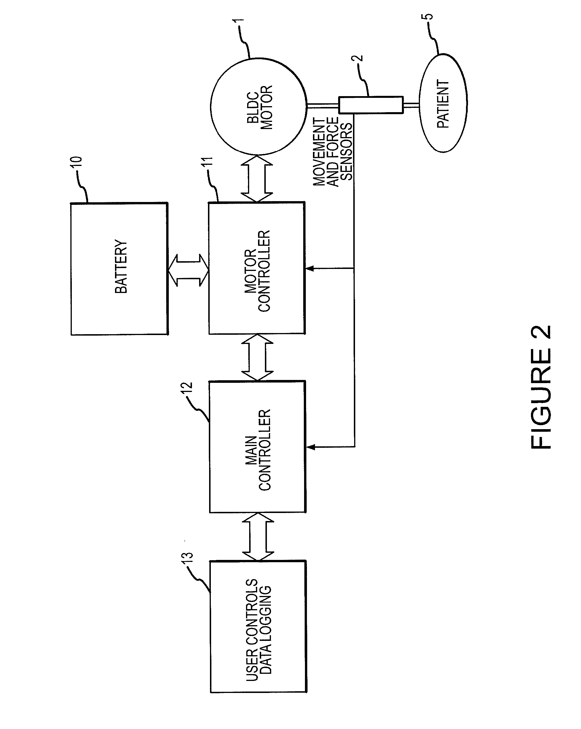
[0012] The controller may further provide the ability to extract and log chest compression data from the system controller, enabling clinical studies and optimization of the system. Internal injuries could be related to, for instance, the depth profile of the compression piston, etc. Logging data would enable research into this topic and others.

Problems solved by technology

Manually performed chest compressions is an extremely exhausting task, and it is practically impossible to give sufficient quality manual CPR during transportation of a patient.
Previously known automatic chest compression devices are designed mainly with respect to (1), and in many cases do not provide a satisfactory balance between (1) and (2).

Method used


Image

  • Servo motor for cpr
  • Servo motor for cpr
  • Servo motor for cpr

Examples


Embodiment Construction

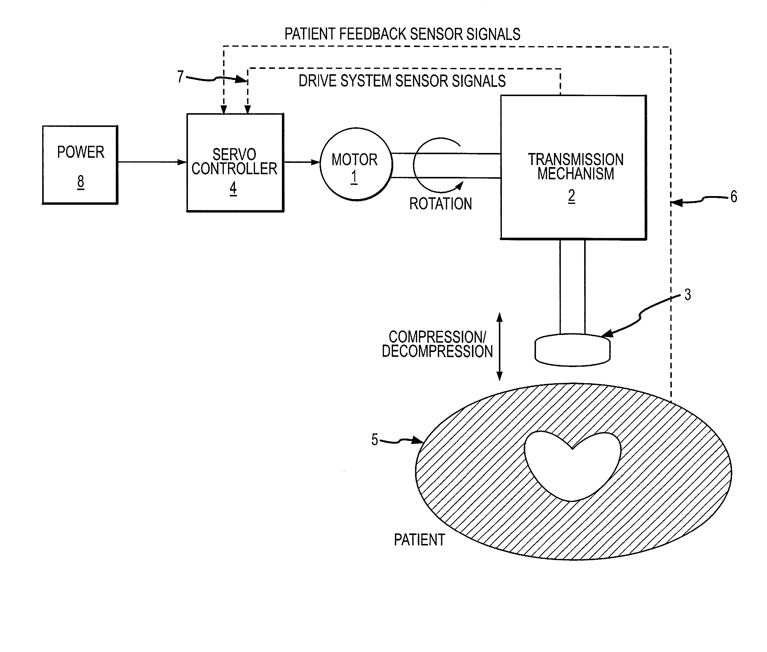
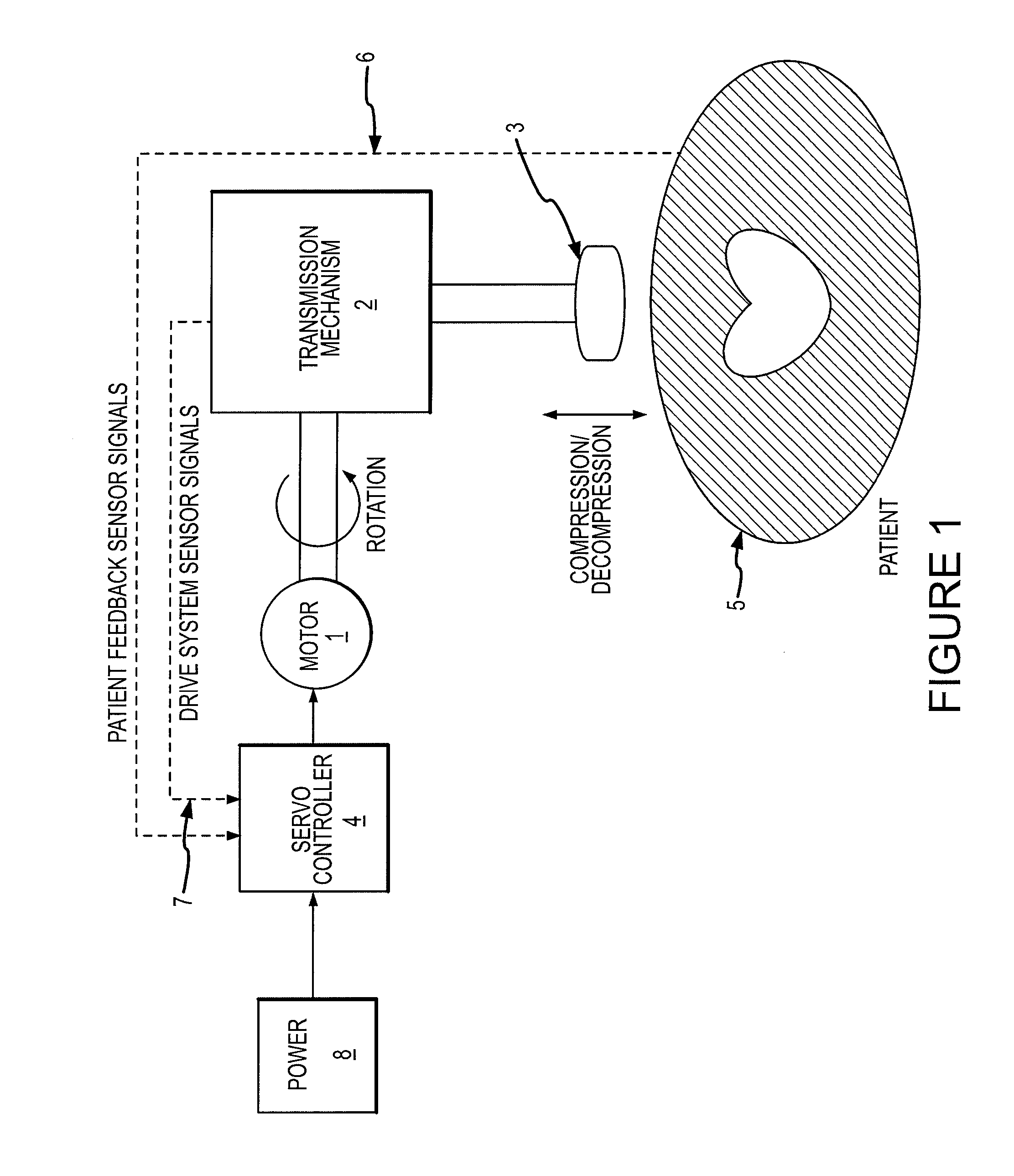
[0020]FIG. 1 shows a block diagram of an embodiment of a chest compression device providing compressions to a patient in a controlled manner. The device comprises a servo motor 1 connected to a transmission mechanism 2 for transforming rotational movement in the motor 1 into a reciprocating movement. The transmission mechanism 2 is connected to a compression element 3, which can, for example, be formed as a plate, a vacuum cup, or a round shaped body. The compression element 3 is driven by the motor 1 to perform compressions. The device may also comprise a servo controller 4, which among other functions controls the motor's operating cycle. The servo controller 4 is adapted to drive the motor 1 with a digital modulated or analog pulse pattern. The pulse pattern may be input to the controller by input means known in the art and may be also calculated by the controller based on force and depth measurements of compressions performed on the patient. The controller may also calculate the...


PUM


Abstract

The invention regards a resuscitation system having a chest compression device to repeatedly compress the chest of a patient and thereafter cause or allow the chest to expand. The device includes an electric motor connected to a compression element. A controller is coupled to the electric motor and causes the motor to actuate the compression element according to a predetermined profile. The controller is further operable to draw the compression element away from a patient's chest upon detecting a malfunction.

Description

CROSS-REFERENCE TO RELATED APPLICATIONS [0001] This application claims the benefit of U.S. Provisional Patent Application No. 60 / 746,993, filed May 11, 2006, and is a continuation-in-part of U.S. patent application Ser. No. 11 / 603,976, filed Nov. 21, 2006. [0002] The entire disclosure of each of the prior applications is considered to be part of the disclosure of the instant application and is hereby incorporated by reference therein.TECHNICAL FIELD [0003] The invention relates generally to apparatus for treating cardiac arrest and, more specifically, chest compression devices. BACKGROUND OF THE INVENTION [0004] Sudden cardiac arrest is a leading cause of death in developed countries in the Western World, like United States and Canada. To increase the chance for survival from cardiac arrest, important aspects are CPR (Cardio Pulmonary Resuscitation) and heart defibrillation given in the first few critical minutes after the incident. CPR is performed to ensure a sufficient flow of ox...

Claims


Application Information

Patent Timeline
IPC IPC(8): A61H31/00
CPCA61H31/004A61H31/005A61H31/006A61H2201/0176A61H2201/018A61H2201/1215A61H2230/207A61H2201/5007A61H2201/5058A61H2201/5061A61H2201/5064A61H2230/04A61H2201/1664Y10S601/08
Inventor HAVARDSHOLM, JOSTEINFOSSAN, HELGESTROMSNES, OYSTEIN
Owner BASF CATALYSTS LLC
Learn More