Bone anchor system utilizing a molded coupling member for coupling a bone anchor to a stabilization member and method therefor

a bone anchor and stabilization member technology, applied in the field of surgical implants for bone and skeletal stabilization, can solve problems such as unsatisfactory stress concentration

Inactive Publication Date: 2007-11-22
WARSAW ORTHOPEDIC INC
View PDF37 Cites 120 Cited by
  • Summary
  • Abstract
  • Description
  • Claims
  • Application Information

AI Technical Summary

Benefits of technology

[0019]FIG. 6 illustrates a cutaway view of an embodiment of a bone anchor system comprising a conventional coupling member that is adapted to accept an interface piece comprising a deformable material, in accordance with an aspect of the present invention;

Problems solved by technology

It has been determined that the use of a conventional coupling member made of biocompatible metal can result in undesirable stress concentrations at various points on the surface of stabilization members made of more flexible materials when in vivo post-operative loads are applied to the stabilization system.

Method used


Image

  • Bone anchor system utilizing a molded coupling member for coupling a bone anchor to a stabilization member and method therefor
  • Bone anchor system utilizing a molded coupling member for coupling a bone anchor to a stabilization member and method therefor
  • Bone anchor system utilizing a molded coupling member for coupling a bone anchor to a stabilization member and method therefor

Examples


Embodiment Construction

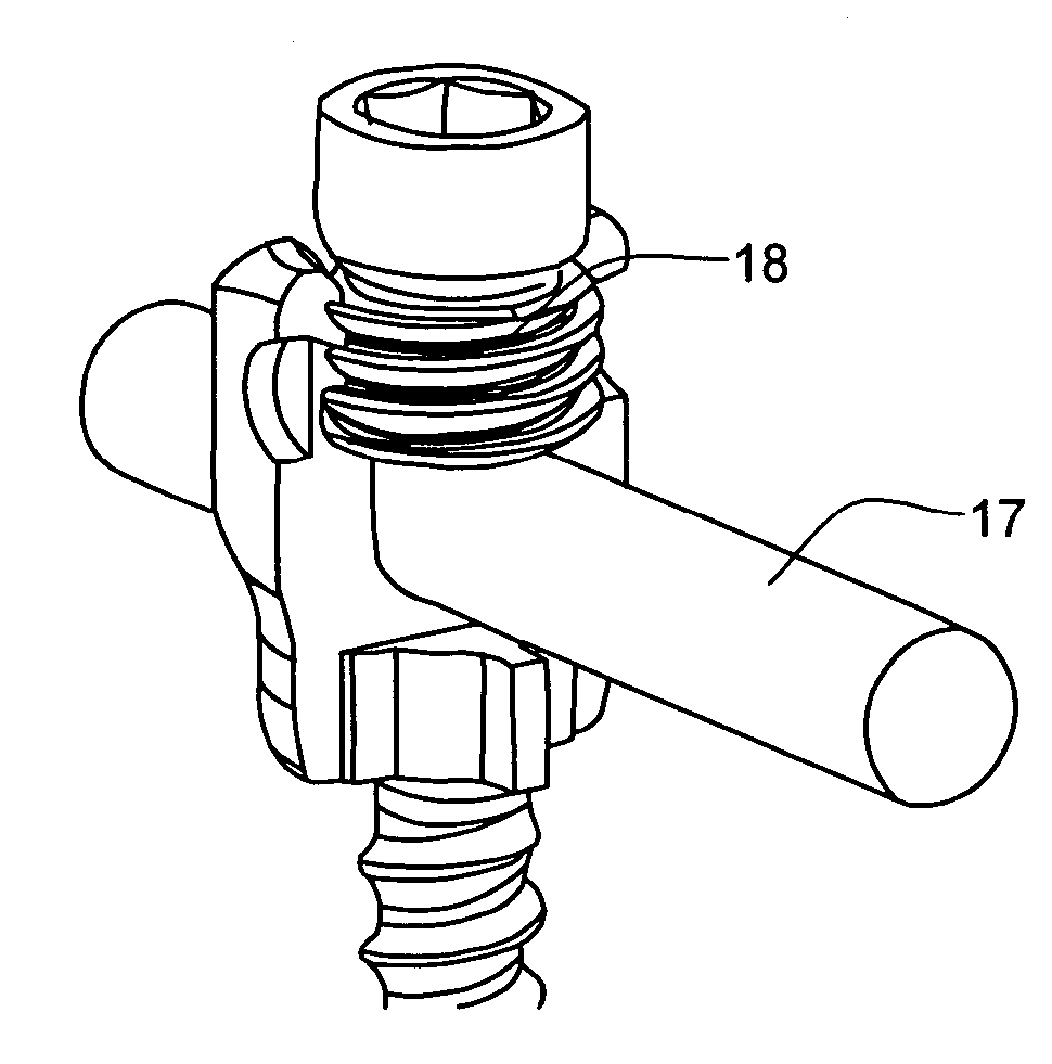
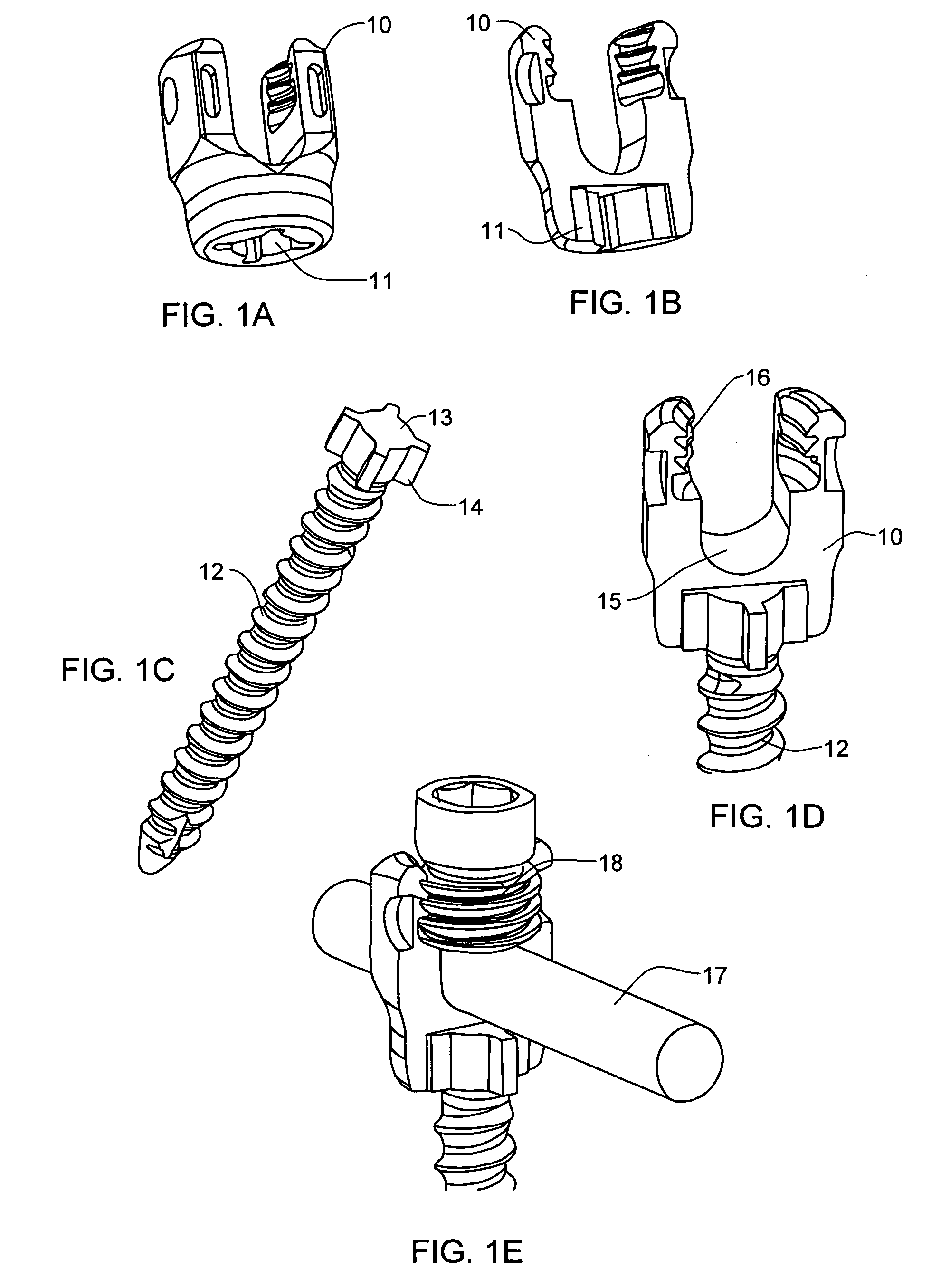
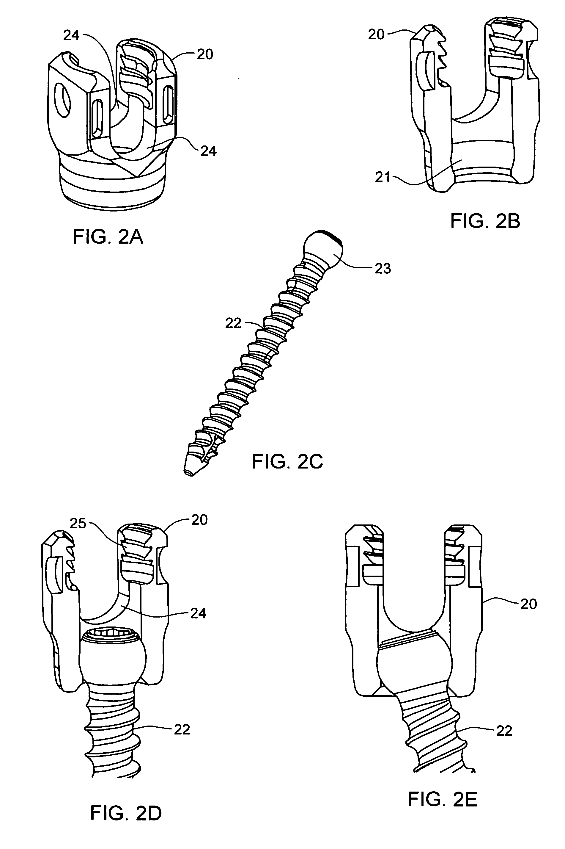
[0022] The present invention is directed to a bone anchor system comprising a bone anchor (e.g., a screw) having an integral head, a stabilization member (e.g. a rod), and a coupling member for coupling the bone anchor to the stabilization member. In one embodiment of a bone anchor system, in accordance with an aspect of the present invention, the coupling member is molded around the integral head of the bone anchor. In accordance with another aspect of the invention, the coupling member provides an interface to a stabilization member (e.g. a rod). The interface provided by the coupling member is less rigid than the bone anchor or metal couplings used in conventional implantable bone anchor systems. For example, the coupling member or at least the interface may be molded from a polyetheretherketone (PEEK) material, which is a high-strength plastic that is radiolucent, non-conducting, and non-magnetic.

[0023] The provision of a less-rigid, deformable interface to the stabilization me...


PUM


Abstract

A bone anchor system including a bone anchor having an integral head, a stabilization member, and a coupling member molded around the integral head of the bone anchor is provided for coupling the bone anchor to the stabilization member. The coupling member includes an interface to the stabilization member. Advantageously, the interface to the stabilization member is made of a deform able material to reduce surface stress concentration in the stabilization member. The interface of the coupling member may be integral to the coupling member, or the interface may be an interface piece that may be inserted into the coupling member. The integral head of a bone anchor may include a molded cap that is formed from a deformable material and configured to provide an interface to the stabilization member.

Description

CROSS-REFERENCE TO RELATED APPLICATIONS / PATENTS [0001] This application contains subject matter which is related to the subject matter of the following application, which is hereby incorporated herein by reference in its entirety: [0002]“Locking Device and Method, for Use in a Bone Stabilization System, Employing a Set Screw Member and Deformable Saddle Member”, J. D. Moore, U.S. Ser. No. ______, co-filed herewith (Attorney Docket No.: P24289.00).TECHNICAL FIELD [0003] The present invention relates generally to surgical implants for bone and skeletal stabilization and, more particularly, to a bone anchor system for coupling a bone anchor to a stabilization member. BACKGROUND OF THE INVENTION [0004] In the field of spinal surgery, for example, it is customary to place implants into vertebrae for a number of reasons, including: (a) correcting an abnormal curvature of the spine; (b) to maintain appropriate vertebral spacing and provide support for broken or otherwise injured vertebrae;...

Claims


Application Information

Patent Timeline
Patent Type & Authority Applications(United States)
IPC IPC(8): A61F2/30
CPCA61B17/7032A61B17/7035A61B17/8605A61B17/7038A61B17/7037A61B17/70A61B17/86
Inventor DEWEY, JONATHAN M.PATTERSON, CHRIS M.
Owner WARSAW ORTHOPEDIC INC
Why Eureka
Try Eureka