
Robot using absolute azimuth and mapping method thereof

Inactive Publication Date: 2007-11-22
SAMSUNG ELECTRONICS CO LTD
View PDF20 Cites 33 Cited by
  • Summary
  • Abstract
  • Description
  • Claims
  • Application Information

AI Technical Summary

Benefits of technology

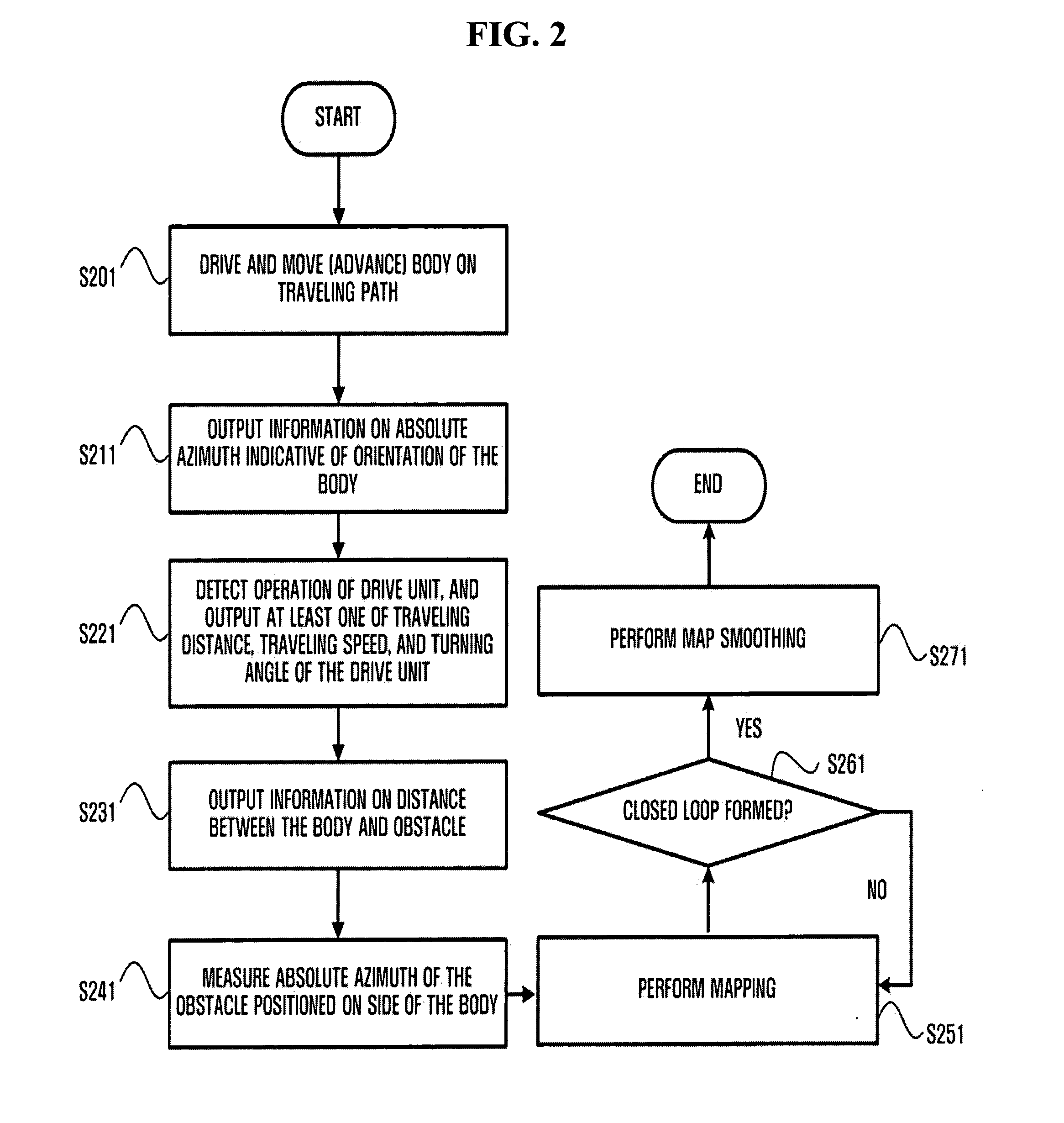
[0015]According to another aspect of the present invention, a method of improving an accuracy of mapping of a specified area, including: advancing a robot along traveling path; outputting information indicating an orientation of the robot; sensing a distance between the robot and an obstacle; determining, using the sensed distance, an absolute azimuth of the obstacle based on an average value of the absolute azimuth indicating an orientation of the body measured for a specified time; mapping the specified area based on the traveling path; and determining whether the traveling path of the body forms a closed loop and smoothing the map when the traveling path of the body forms a closed loop.

Problems solved by technology

When the robot performs the successive operations using the gyro and the encoder, an azimuth error is accumulated as time elapses.
Therefore, the robot may produce an inaccurate map.
For example, when the position of the robot is estimated, an error occurs due to the slippage or mechanical drift of wheels.
Although such an error is insignificant, the accumulated error may cause a serious problem.
However, this method has a problem that the relative distance and angle are detected from the initial absolute position, and this causes errors to be accumulated.

Method used


Image

  • Robot using absolute azimuth and mapping method thereof
  • Robot using absolute azimuth and mapping method thereof
  • Robot using absolute azimuth and mapping method thereof

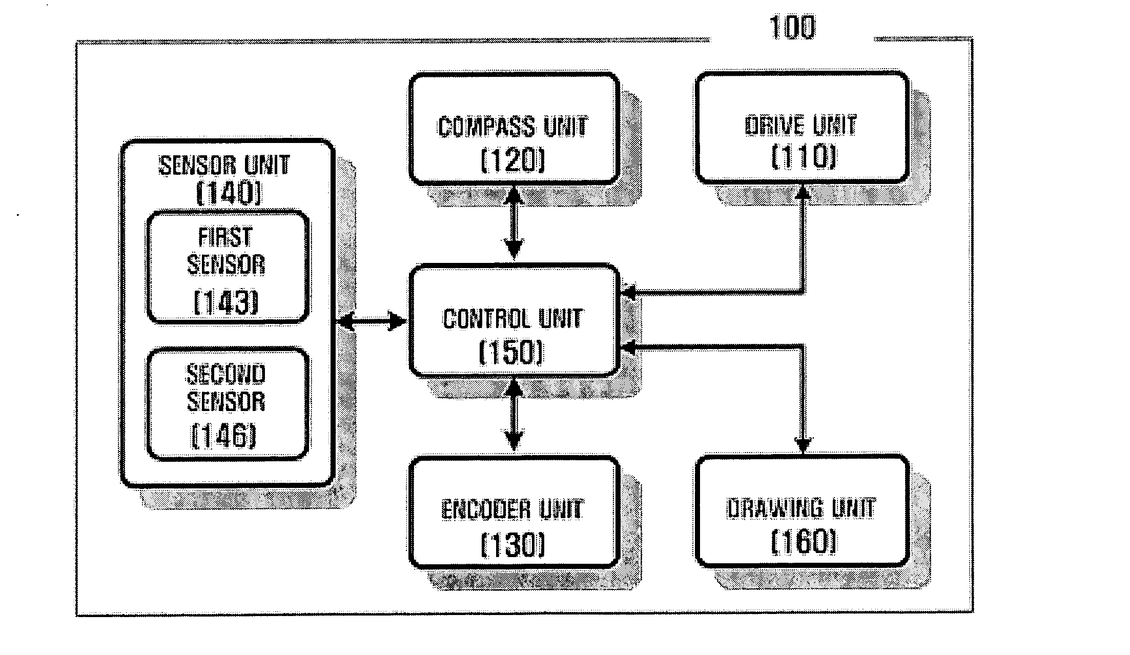
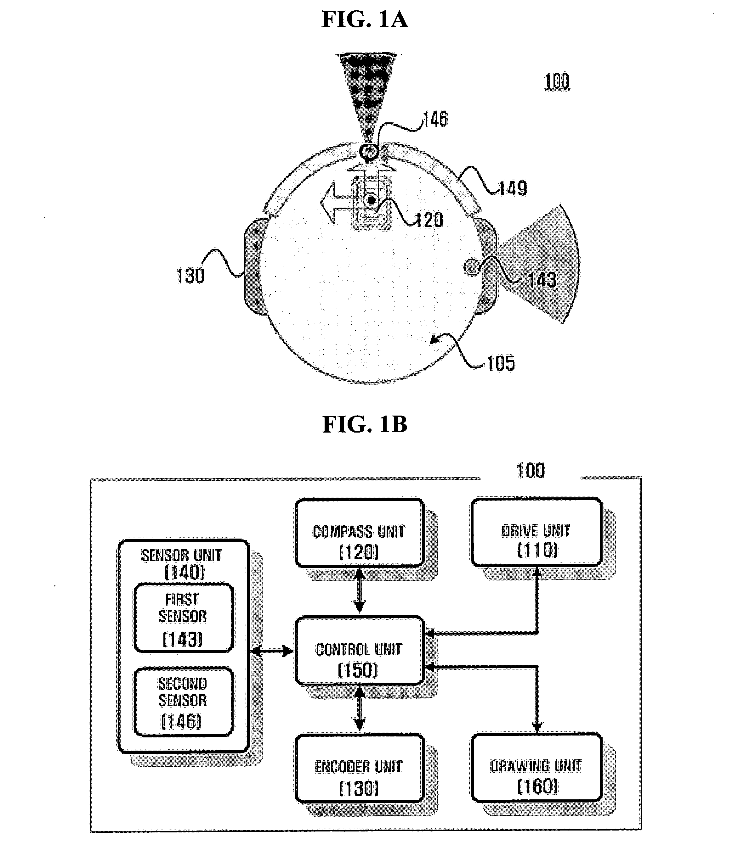
Examples


Embodiment Construction

[0026]Reference will now be made in detail to embodiments of the present invention, examples of which are illustrated in the accompanying drawings, wherein like reference numerals refer to the like elements throughout. The embodiments are described below in order to explain the present invention by referring to the figures.

[0027]FIGS. 1A and 1B are views illustrating a configuration of a robot 100 using an absolute azimuth, according to an embodiment of the present invention.

[0028]FIG. 1A is a plan view illustrating an example of a configuration of the robot 100. FIG. 1B is a block diagram illustrating components of the robot 100.

[0029]Referring to FIGS. 1A and 1B, the robot 100 according to the present embodiment includes a drive unit 110 driving a body 105, a compass unit 120, an encoder unit 130, a sensor unit 140, a control unit 150, and a drawing unit 160.

[0030]The drive unit 110 moves the body 105 under the control of the control unit 150, which will be described hereinafter. ...


PUM


Abstract

A robot using an absolute azimuth to navigate and a mapping method thereof. The robot includes a control unit controlling a traveling direction of a body of the robot by using the absolute azimuth, which indicates an orientation of the body with respect to a specified reference axis, and a drive unit moving the body under the control of the control unit.

Description

CROSS-REFERENCE TO RELATED APPLICATION[0001]This application is based on and claims priority from Korean Patent Application No. 10-2006-0043988, filed on May 16, 2006 in the Korean Intellectual Property Office, the disclosure of which is incorporated herein by reference.BACKGROUND OF THE INVENTION[0002]1. Field of the Invention[0003]The present invention relates to a robot using an absolute azimuth and a mapping method thereof and, more particularly, to a robot using an absolute azimuth to navigate and a mapping method thereof, in which the traveling path of a robot body can be controlled using the absolute azimuth and the mapping of a specified area can be promptly performed.[0004]2. Description of Related Art[0005]Recently, with the development of robotics and related technologies, diverse types of robots have appeared. In particular, self-driving robots have been developed to perform domestic tasks for humans.[0006]Generally, a robot includes a drive part (e.g., wheels) equipped ...

Claims


Application Information

Patent Timeline
IPC IPC(8): G06F19/00G05D1/02
CPCG05D1/0242G05D1/0274G05D1/0272G05D1/0255B25J9/16B25J13/08
Inventor BANG, SEOK-WONLEE, SU-JINN
Owner SAMSUNG ELECTRONICS CO LTD
Learn More