
Door Threshold Vacuum

a vacuum and door threshold technology, applied in the field of new vacuum systems, can solve the problems of large housings, large design modifications to existing entryways, and impractical use in other than industrial settings, and achieve the effects of reducing the size, component count, and the cost of operation and maintenan

Active Publication Date: 2007-11-29
JUNELL COREY
View PDF27 Cites 11 Cited by
  • Summary
  • Abstract
  • Description
  • Claims
  • Application Information

AI Technical Summary

Benefits of technology

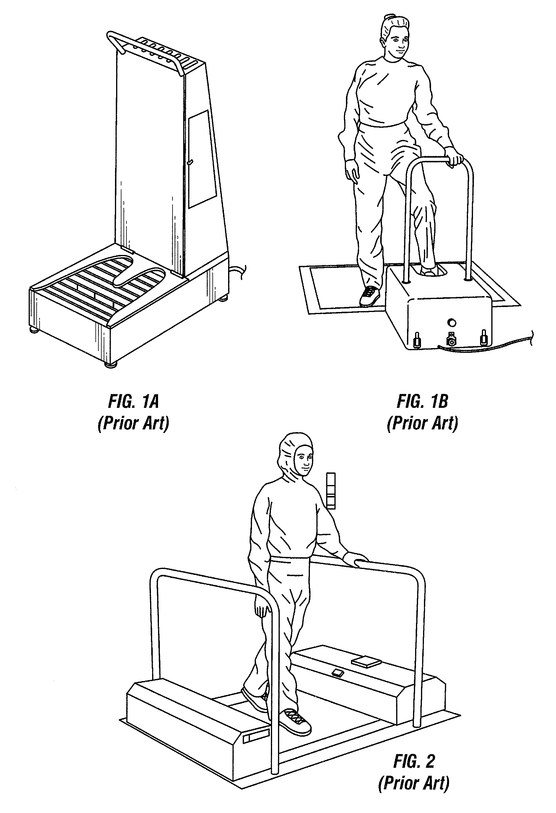
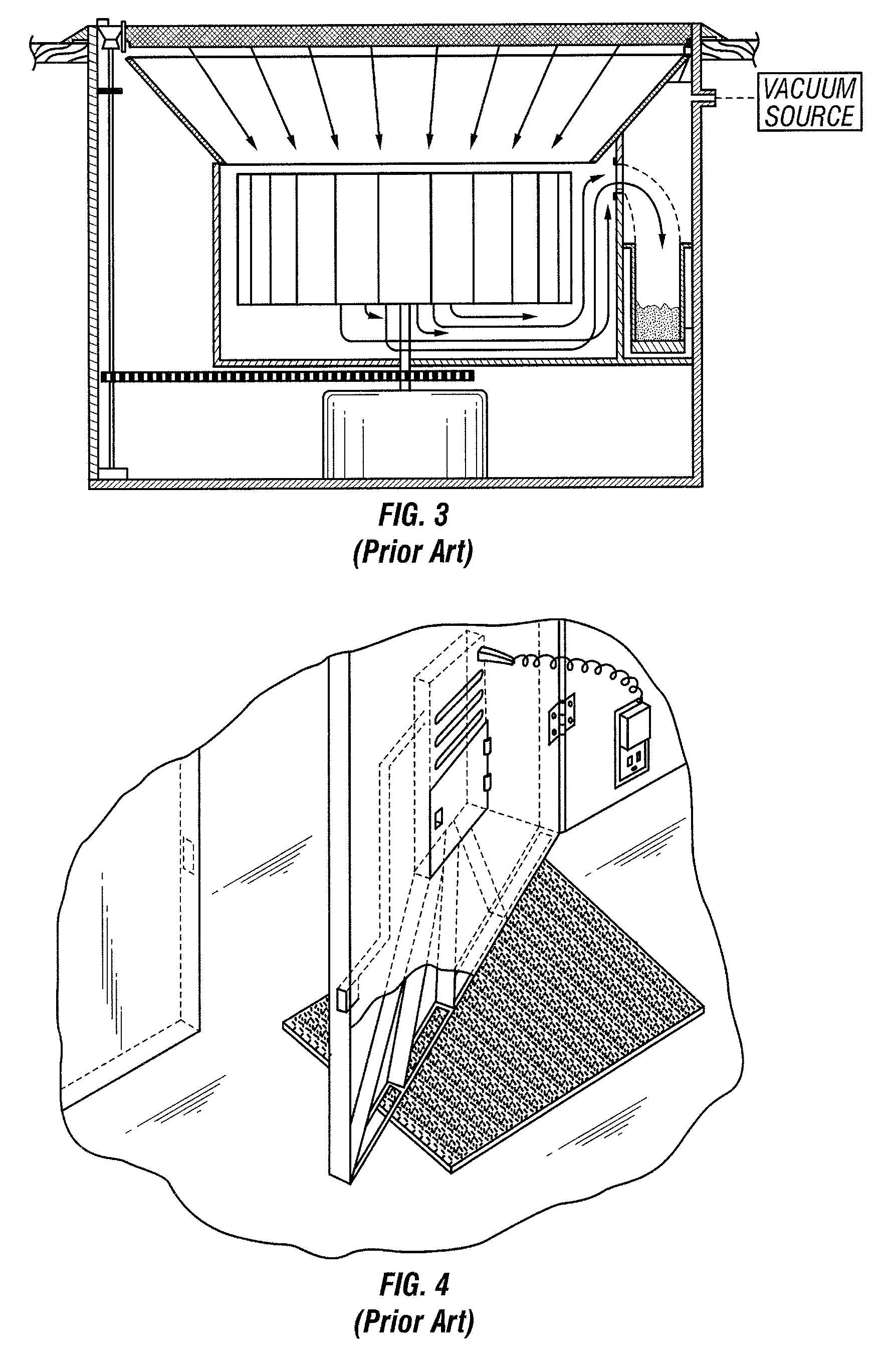
[0015]The present invention is directed to a footwear cleaning device or apparatus that can be used in residential, commercial, or even industrial settings. Prior art designs tend to require extensive modification to existing entryways or require large housings if used in a portable embodiment. Because of this, they tend to be impractical for use in other than industrial settings. The present invention is designed to overcome this problem and others by reducing the size, component count, and expense related to operation and maintenance.
[0016]Accordingly, it is one general object of the invention to provide a footwear cleaning device that can be easily installed in the threshold area of an existing doorway, or else made portable for use in a variety of situations.
[0017]It is another general object of the invention to provide a footwear cleaning device that minimizes the problem of excessive maintenance and expense associated with prior art devices by reducing the number of moving parts and eliminating excessive components that are designed to wear and require frequent replacement.
[0018]It is another general object of the invention is to provide a footwear cleaning device that efficiently cleans both the bottom and the welt of a shoe, and also dries the shoe if wet.
[0019]It is another general object of the invention is to provide a footwear cleaning device that is more aesthetically pleasing.
[0020]Yet another general object of the invention is to provide a footwear cleaning device that can be powered from either an AC or DC power source, thus lending to its flexibility and portability.

Problems solved by technology

Prior art designs tend to require extensive modification to existing entryways or require large housings if used in a portable embodiment.
Because of this, they tend to be impractical for use in other than industrial settings.

Method used


Image

  • Door Threshold Vacuum
  • Door Threshold Vacuum
  • Door Threshold Vacuum

Examples


first embodiment

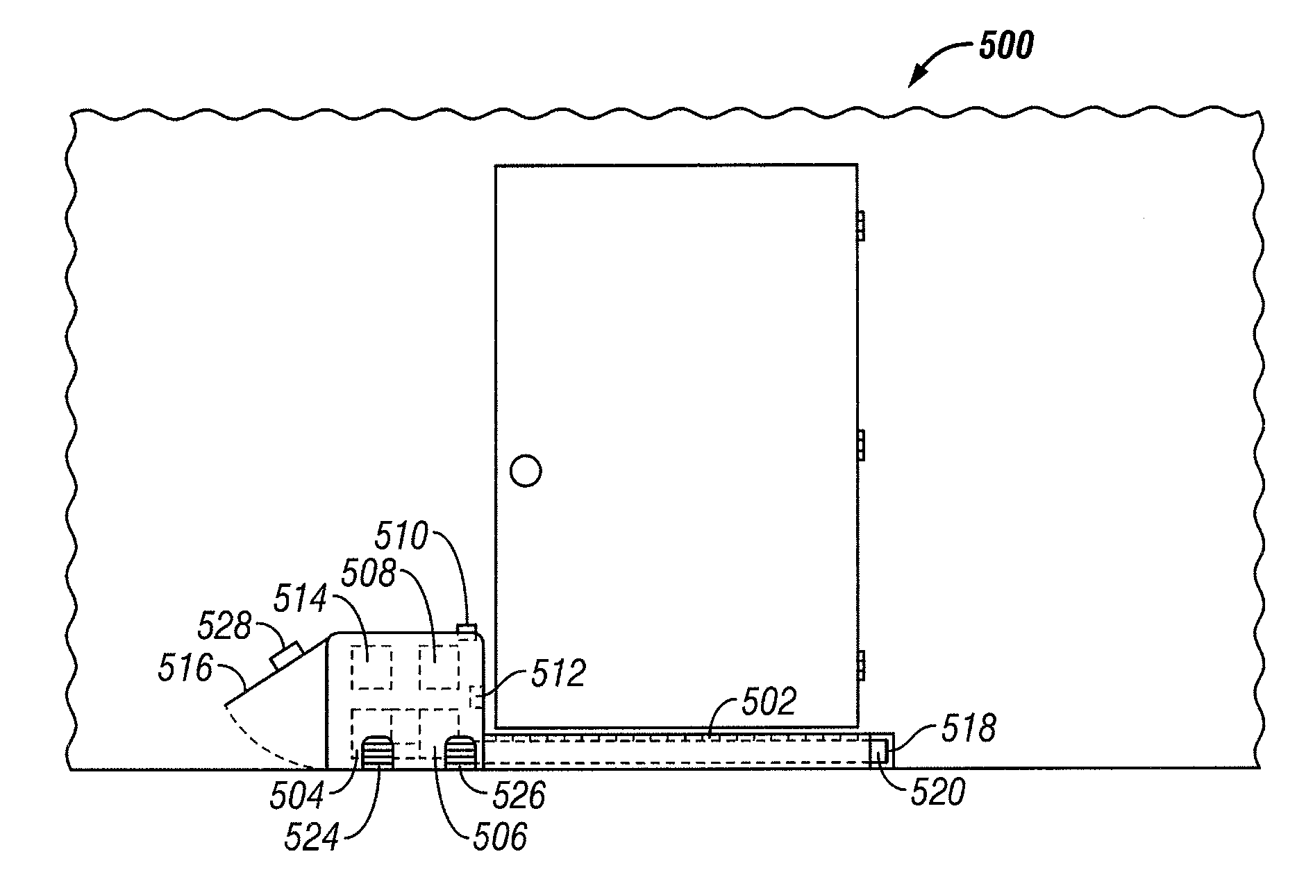
[0053]FIG. 5 illustrates a door threshold vacuum 500 as it would appear when mounted as an integral part of a door threshold. FIG. 5A illustrates how the embodiment of the device might appear to a pedestrian as they approach the door. FIG. 5B illustrates a top-down view of the embodiment to provide further detail of its elements. When the pedestrian opens the door and steps upon the removable tray 502, the door threshold vacuum 500 activates and pulls the dirt and debris from the bottom of the pedestrian's footwear. Thus, the dirt and debris are trapped within the apparatus, significantly reducing and possibly eliminating the amount of dirt and debris that is normally carried into a building upon the footwear of one who enters.

[0054]With reference to FIG. 5, the door threshold vacuum 500 apparatus illustrated in this first embodiment is an integral portion of the threshold of an entryway door. Because it is integral, the door threshold vacuum 500 includes a doorsill plate 522 that c...

second embodiment

[0065]FIG. 7 utilizes a power switch 510 that can have either two positions (on / off) or more, such as when an additional sensor is used to provide for automated use. For instance, an activation sensor 512 may be incorporated to detect when a pedestrian is standing on the tray 502. The activation sensor 512 could be a photodetector, or some other type of device that can transform the stimulus of the pedestrian stepping onto the tray 502 into a signal that allows the vacuum source controller 508 to operate. In another embodiment the activation sensor 512 could be triggered by the weight of the pedestrian stepping upon the tray 502. In still further embodiments, such as one designed for continuous operation, the activation sensor 512 may not be utilized and the vacuum source controller 508 may be controlled directly by the power switch 510.

third embodiment

[0066]FIG. 8 illustrates the present invention, configured as a portable door threshold vacuum device for commercial and industrial use. In this embodiment, it is likely that size will not be as much of an issue. Therefore, the internal components (power source 514, vacuum source controller 508, and vacuum source 504) may be of heavier grade for more strenuous and potentially continuous operation. Operation and maintenance of this embodiment would be similar to the lighter duty configuration as described above and illustrated in FIG. 7.

[0067]In view of the foregoing, the door threshold vacuum 500 serves needs not met by prior art devices. It can be used in residential, commercial, and even industrial settings to efficiently remove dirt and debris from a pedestrian's footwear. In addition, it does not require extensive modification to existing entryways in its permanent installation embodiment or else require large housings in a portable embodiment. Because of this, it is more practi...


PUM


Abstract

An apparatus for automatically cleaning dirt and debris from a pedestrian's footwear. The apparatus can be an integral portion of the entryway door's threshold or else can be made portable. The pedestrian steps upon a removable tray and activates a vacuum source. The vacuum source pulls the dirt and debris from the pedestrian's footwear through a multitude of openings in the removable tray. The dirt and debris is captured within the tray (large particles) and debris collection container (smaller particles) for later disposal. The apparatus cleans the welts and also provides a means for drying wet footwear. The apparatus can be either AC or DC powered and can be automated to only operate when a pedestrian is standing upon the tray, can operate continuously, or can be manually switched on and off.

Description

CROSS-REFERENCE TO RELATED APPLICATIONS[0001]Not ApplicableSTATEMENT REGARDING FEDERALLY SPONSORED RESEARCH OR DEVELOPMENT[0002]Not ApplicableTHE NAMES OF THE PARTIES TO A JOINT RESEARCH AGREEMENT[0003]Not ApplicableINCORPORATION-BY-REFERENCE OF MATERIAL SUBMITTED ON A COMPACT DISC[0004]Not ApplicableBACKGROUND OF THE INVENTION[0005]1. Field of the Invention[0006]The present invention relates generally to a novel vacuum system, and more specifically, to an apparatus for cleaning dust, dirt, and debris from the footwear of a pedestrian entering a building.[0007]2. Description of Related Art[0008]A variety of proposals have previously been made to control the tracking of dust, dirt, and debris caused by the footwear of a pedestrian entering a building. The most basic means is a doormat upon which the pedestrian wipes his or her shoes prior to entering. However, even when the shoes are relatively clean the doormat does little to remove and retain any debris and often contaminates the s...

Claims


Application Information

Patent Timeline
Patent Type & Authority Applications(United States)
IPC IPC(8): A47L5/38
CPCA47L23/263A47L5/38A47L23/02
Inventor JUNELL, COREY
Owner JUNELL COREY
Learn More