Systems and methods for primary-side regulation in off-line switching-mode flyback power conversion system

Active Publication Date: 2010-02-04
ON BRIGHT ELECTRONICS SHANGHAI
View PDF2 Cites 37 Cited by
  • Summary
  • Abstract
  • Description
  • Claims
  • Application Information

AI Technical Summary

Benefits of technology

[0023]Many benefits are achieved by way of the present invention over conventional techniques. Certain embodiments of the present invention reduce parts count and/or system cost. Some embodiments of the present invention improve reliability and/or effic

Problems solved by technology

Such arrangement usually increases the system cost, size, and power consumption.
Therefore, the scheme as described above often has poor load-voltage regulation due to the voltage

Method used


Image

  • Systems and methods for primary-side regulation in off-line switching-mode flyback power conversion system
  • Systems and methods for primary-side regulation in off-line switching-mode flyback power conversion system
  • Systems and methods for primary-side regulation in off-line switching-mode flyback power conversion system

Examples


Example

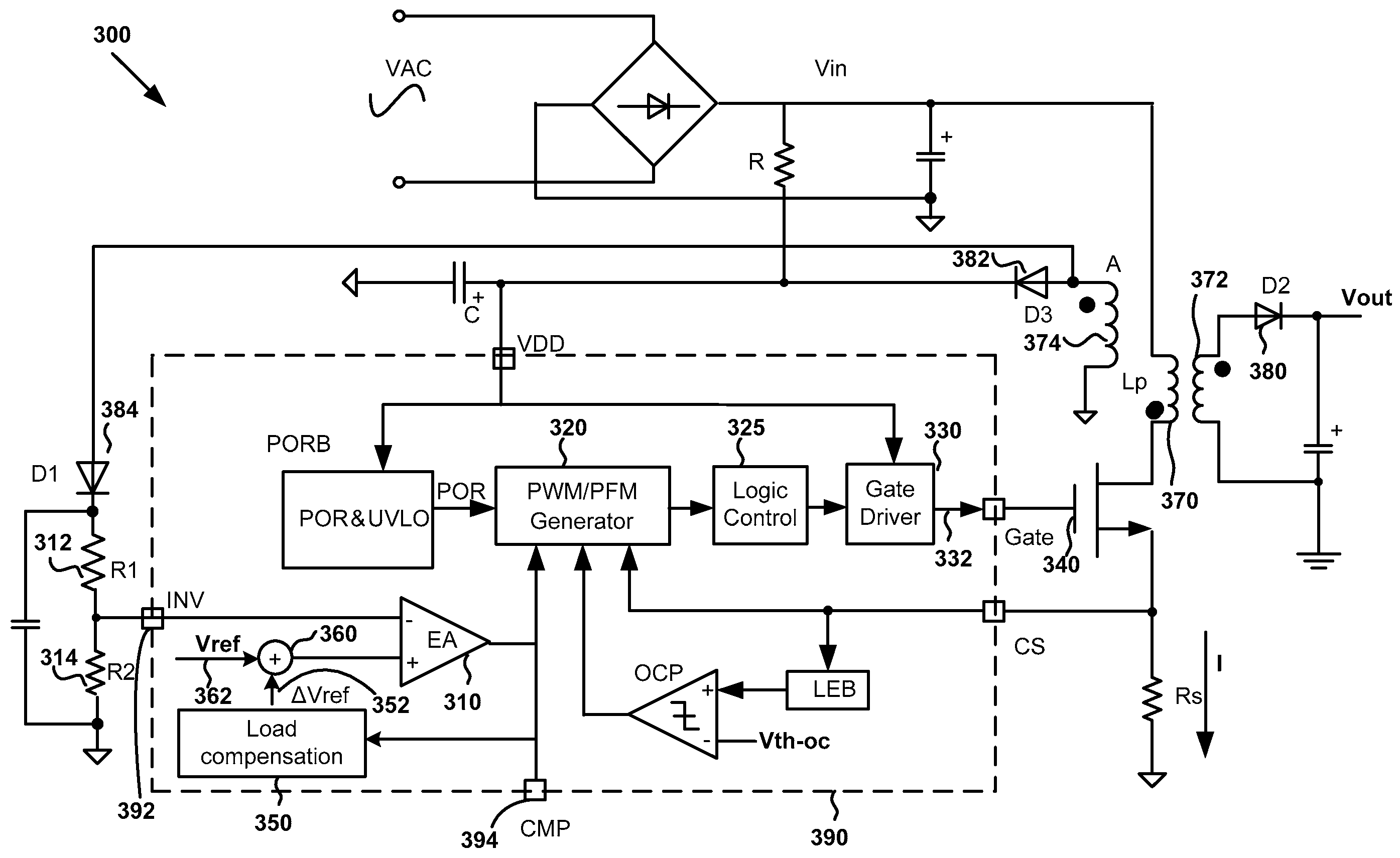
[0034]The present invention is directed to switching-mode power conversion systems. More particularly, the invention provides systems and methods for primary-side regulation with load compensation. Merely by way of example, the invention has been applied to off-line switching-mode flyback power conversion systems. But it would be recognized that the invention has a much broader range of applicability.

[0035]FIG. 3 is a simplified diagram showing a switching-mode power conversion system with primary-side control and load compensation according to one embodiment of the present invention. This diagram is merely an example, which should not unduly limit the scope of the claims. One of ordinary skill in the art would recognize many variations, alternatives, and modifications. A switching-mode power conversion system 300 includes an error amplifier 310, resistors 312 and 314, a PWM / PFM generator 320, a logic control component 325, a gate driver 330, a switch 340, a load compensation compon...


PUM


Abstract

Switching-mode power conversion system and method thereof. The system includes a primary winding configured to receive an input voltage, and a secondary winding coupled to the primary winding and configured to, with one or more first components, generate, at an output terminal, an output voltage and an output current. Additionally, the system includes an auxiliary winding coupled to the secondary winding and configured to, with one or more second components, generate, at a first terminal, a detected voltage. Moreover, the system includes an error amplifier configured to receive the detected voltage and a first reference voltage and generate an amplified voltage based on at least information associated with a difference between the detected voltage and the first reference voltage. Also, the system includes a compensation component configured to receive the amplified voltage and generate a second reference voltage based on at least information associated with the amplified voltage.

Description

1. CROSS-REFERENCES TO RELATED APPLICATIONS[0001]This application claims priority to U.S. Provisional No. 61 / 084,982, filed Jul. 30, 2008, commonly assigned, incorporated by reference herein for all purposes.2. BACKGROUND OF THE INVENTION[0002]The present invention is directed to switching-mode power conversion systems. More particularly, the invention provides systems and methods for primary-side regulation with load compensation. Merely by way of example, the invention has been applied to off-line switching-mode flyback power conversion systems. But it would be recognized that the invention has a much broader range of applicability.[0003]Flyback converters have been used extensively for its simple structure and low cost in low-power power supplies. But in conventional flyback converters, the output-voltage regulation is often performed with secondary-side feedback, using an isolated arrangement of opto-coupler and shunt regulator (e.g., TL431). Such arrangement usually increases t...

Claims


Application Information

Patent Timeline
IPC IPC(8): H02M3/335
CPCH02M3/33507H02M2001/0025H02M2001/0022H02M1/0022H02M1/0025
Inventor FANG, LIEYI
Owner ON BRIGHT ELECTRONICS SHANGHAI
Why Eureka
Try Eureka