
Fuel heating system for turbine engines

Inactive Publication Date: 2007-11-29
SIEMENS ENERGY INC
View PDF17 Cites 1 Cited by
  • Summary
  • Abstract
  • Description
  • Claims
  • Application Information

AI Technical Summary

Benefits of technology

[0004]The fuel heating system may include one or more plates for controlling the flow of exhaust gases into the fuel heating chamber. In at least one embodiment, two plates may be used and include one or more orifices. The orifices may be aligned to enable exhaust gases to flow through the plate. The plates may be moved relative to each other to reduce or increase the size of the openings created by the two plates overlapping the exhaust gas orifices.
[0006]An advantage of this invention is that fuel heating may be accomplished with exhaust gases without the need to reduce the velocity of exhaust gas flow. Instead, the exhaust gases may be passed through the fuel heating chamber directly from the exhaust stack.
[0007]Another advantage of this invention is that direct flow through of exhaust gases is not required to heat fuel in the system. Rather, fuel may be heated to about 550 degrees Fahrenheit with exhaust gases of about 1,100 degrees Fahrenheit using an open valve system in which exhaust gases may flow into and out of the fuel heating chamber through exhaust gas orifices in the plates.

Problems solved by technology

However, many of these conventional heating systems place a load on the turbine engines to which they are attached, thereby decreasing the efficiency of the turbine engines.

Method used


Image

  • Fuel heating system for turbine engines
  • Fuel heating system for turbine engines
  • Fuel heating system for turbine engines

Examples


Embodiment Construction

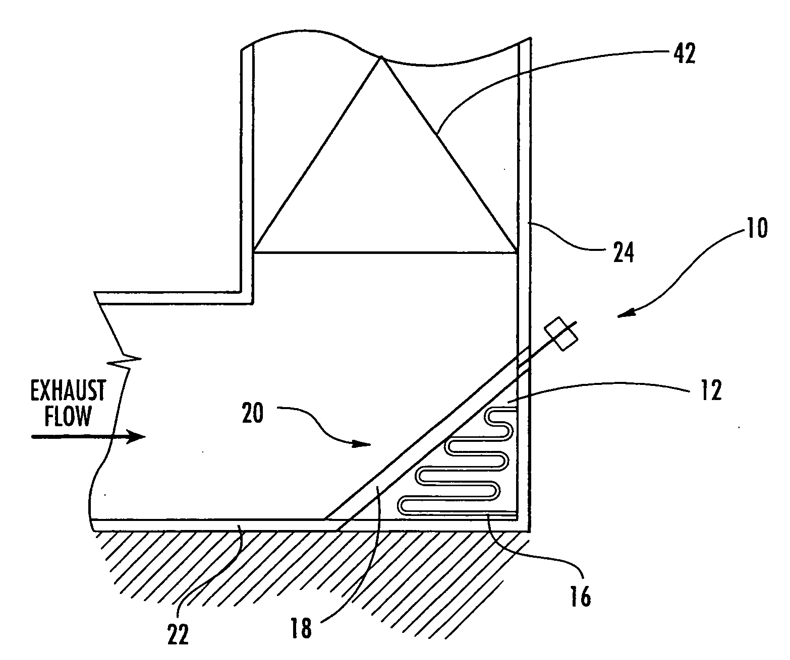
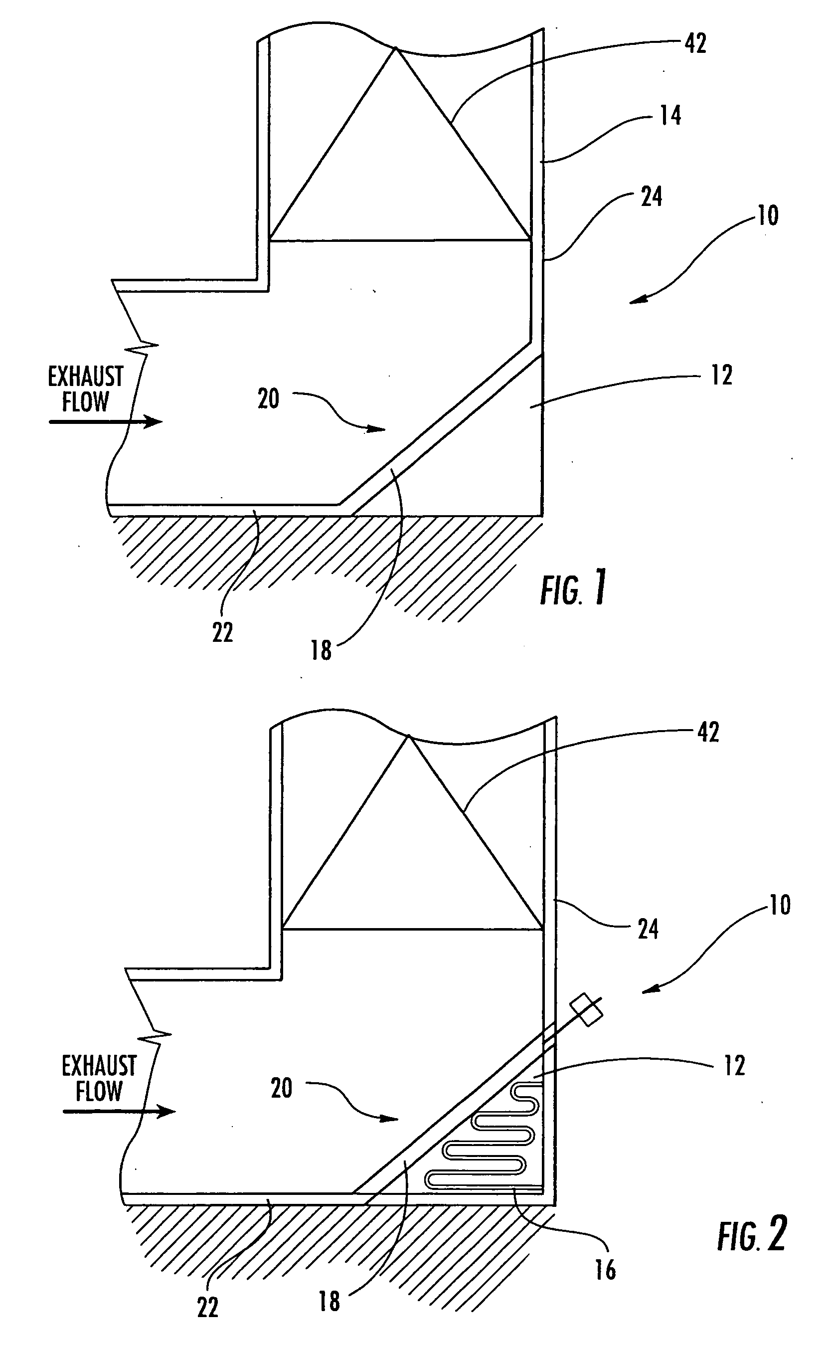
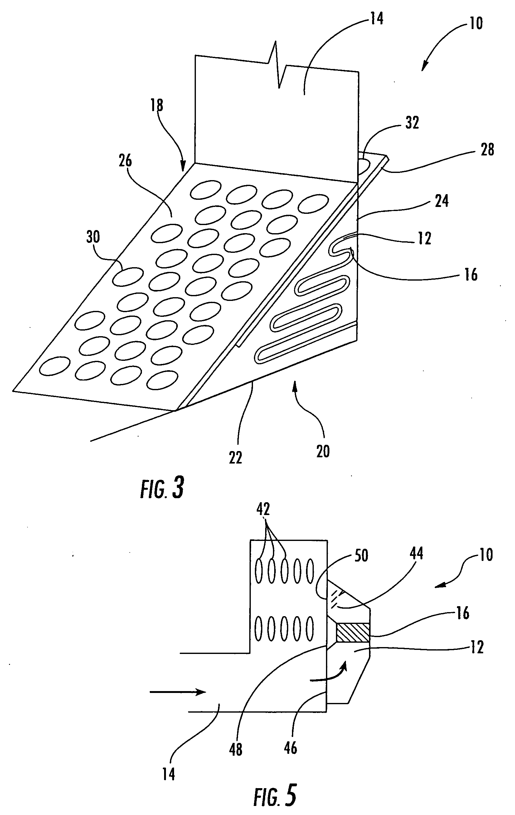
[0015]As shown in FIGS. 1-5, the invention is directed to a fuel heating system 10 for a turbine engine. The fuel heating system 10 may be configured to increase the temperature of fuel usable in a turbine engine by using heat found in exhaust gases of the turbine engine. In particular, the fuel heating system 10 may be formed from one or more fuel heating chambers 12 in communication with an exhaust stack 14 of a turbine engine. The fuel heating system 10 may be configured to allow exhaust gases to flow through the fuel heating chamber 12 to heat the fuel. The fuel heating system 10 may also include one or more conduits 16 positioned in the fuel heating chamber 12. The conduit 16 may be configured to receive fuel from one or more fuel sources, such as, but not limited to, a fuel tank, at a first temperature, allow the fuel to flow through the conduit 16, and exhaust the fuel at a second temperature that is higher than the first temperature.

[0016]As shown in FIGS. 1-3, the fuel heat...


PUM


Abstract

A fuel heating system for fuel usable in a turbine engine. The fuel heating system may include at least one fuel heating chamber in communication with an exhaust stack of a turbine engine. The fuel heating chamber may be configured to allow exhaust gases to flow through the at least one fuel heating chamber. The fuel heating system may also include at least one conduit positioned in the fuel heating chamber. The conduit may be configured to receive fuel from a fuel source at a first temperature, allow the fuel to flow through the conduit, and exhaust the fuel at a second temperature that is higher than the first temperature.

Description

FIELD OF THE INVENTION[0001]This invention is directed generally to turbine engines, and more particularly to fuel systems of turbine engines.BACKGROUND[0002]It is known that in thermal power turbine engines, complete combustion of fuel is desired. In addition, it has further been determined that the efficiency of a turbine engine may be increased by heating fuel before the fuel is ignited in a turbine engine. Numerous heating systems have been created to heat fuel before ignition. However, many of these conventional heating systems place a load on the turbine engines to which they are attached, thereby decreasing the efficiency of the turbine engines. Thus, a need exists for an efficient fuel heating system for turbine engines.SUMMARY OF THE INVENTION[0003]This invention is directed to a fuel heating system for a turbine engine. The fuel heating system may be configured to increase the temperature of fuel usable in a turbine engine by using heat in exhaust gases of the turbine engi...

Claims


Application Information

Patent Timeline
IPC IPC(8): F02C7/08F02C7/26
CPCF02C7/224F01D25/30
Inventor PUTNAM, ROBERT A.
Owner SIEMENS ENERGY INC
Learn More