Alternative helical flow control device for polymer injection in horizontal wells

Active Publication Date: 2018-01-11
BAKER HUGHES INC
View PDF2 Cites 1 Cited by
  • Summary
  • Abstract
  • Description
  • Claims
  • Application Information

AI Technical Summary

Benefits of technology

The patent describes a device that helps to balance the flow of polymer during injection in a way that reduces shear effects on the polymer. This device has a design that reduces the velocity of the polymer through a broad zig-zag pattern using a wide inlet plenum that is oriented circumferentially. The device can be used for various polymers and can be adapted for different production needs. Another embodiment of the device includes one or more stacked spiral paths with a tapered shape that gradually increases the polymer velocity and eliminates rapid acceleration as the flow enters the spiral path.

Problems solved by technology

Uneven drainage may result in undesirable conditions such as invasion of a gas cone or water cone.
In like fashion, a water cone may cause an in-flow of water into the oil production flow that reduces the amount and quality of the produced oil.
Therefore, fluid between the formation and the wellbore may not flow evenly through the inflow control devices.
Such devices are relatively expensive and include moving parts, which require maintenance and may not be very reliable over the life of the wellbore.
The benefits of polymer flooding and FCDs has been well demonstrated, however the combination of the two technologies has yet to be fully realized.
The cause of FCDs not being as utilized in polymer injection application is due to the severe degradation of the polymer through devices.
However as the polymer viscosity increases the frictional effects increase, this becomes much more critical in long horizontal wellbores.
Hence this impacts the recovery efficiency.
However the problem with most flow control systems is that it shears the polymer affecting the polymer viscosity.
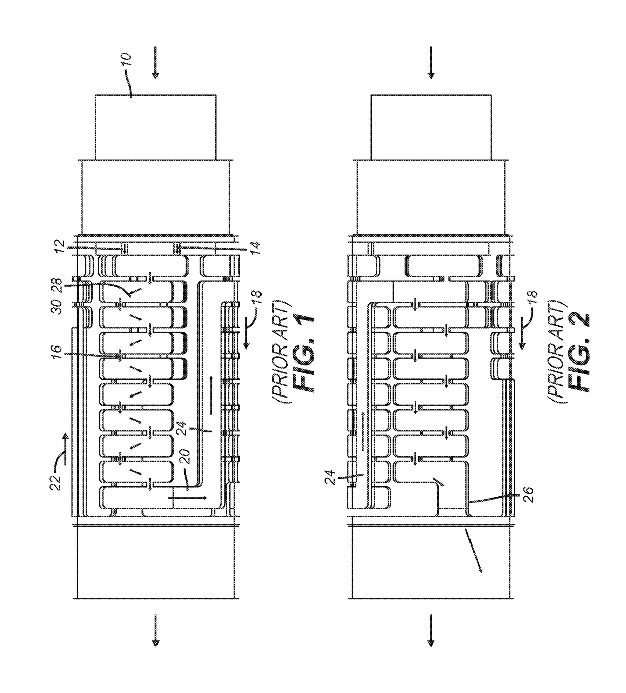
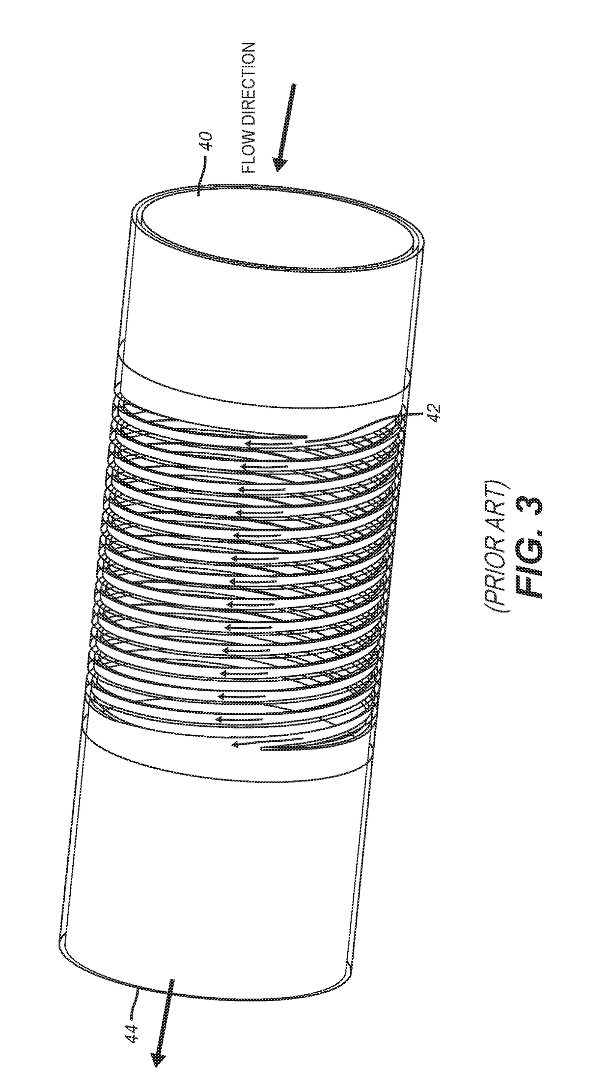
The problem with using such a device or an alternative device shown in FIG. 3 is that there are high velocity regions which cause fluid shearing that if polymer was used through such devices for balancing flow in an injection application, the result would be excessive shear that adversely affects the viscosity of the polymer.

Method used


Image

  • Alternative helical flow control device for polymer injection in horizontal wells
  • Alternative helical flow control device for polymer injection in horizontal wells
  • Alternative helical flow control device for polymer injection in horizontal wells

Examples


Embodiment Construction

[0024]FIG. 4 shows the flow path in the device without the outer housing for greater clarity. The inlet 60 extends between opposed ends 62 and 64 in between which is a height 66 so that the inlet flow represented by arrows is aligned with the crescent-shaped opening or slot that defines the inlet 60. From there the flow goes axially into passage 70 as indicated by arrow 72 and then turns circumferentially into passage 74 as indicated by arrow 76. Transition passage 78 is axially and circumferentially offset from passage 74 to induce the zig-zag flow pattern that repeats as the flow goes back and forth axially as it progresses circumferentially until reaching passage 82 to move into axial path 84 for continuation to the outlet 86 which has the same crescent shape of inlet 60 and results in flow indicated by arrows 88 exiting axially from the outlet 86 to minimize the exit velocity from the broad outlet and elimination of turns using the axial flow out of outlet 86 as indicated by arr...


PUM


Abstract

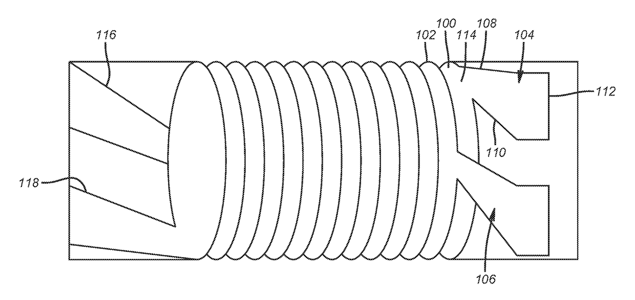
The flow control device comprises one or more stacked spiral paths where the shape of an inlet to an end of a spiral has a taper on one or more sides to gradually increase the polymer velocity to eliminate rapid acceleration points as the flow enters the spiral path. The entrance with its taper can be curved to get into the spiral. The spiral can be entered tangentially or radially or axially.

Description

RELATED APPLICATION DATA[0001]This application is a continuation in part of application Ser. No. 15 / 205,631, filed on Jul. 8, 2016, and incorporated herein by reference in its entirety.FIELD OF THE INVENTION[0002]The field of the invention is flow control devices that balance flow and more particularly devices configured to minimize shear effects that adversely affect viscosity of injected polymers.BACKGROUND OF THE INVENTION[0003]Hydrocarbons such as oil and gas are recovered from a subterranean formation using a well or wellbore drilled into the formation. In some cases the wellbore is completed by placing a casing along the wellbore length and perforating the casing adjacent each production zone (hydrocarbon bearing zone) to extract fluids (such as oil and gas) from such a production zone. In other cases, the wellbore may be open hole. One or more flow control devices are placed in the wellbore to control the flow of fluids into the wellbore. These flow control devices and produc...

Claims


Application Information

Patent Timeline
IPC IPC(8): E21B43/12E21B34/06E21B33/12E21B43/14E21B43/20E21B43/32
CPCE21B43/12E21B34/06E21B43/20E21B33/12E21B43/32E21B43/14E21B43/16
Inventor GOHARI, KOUSHAJUTILA, HEIKKI ARMASMASCAGNINI, CARLOSHARPER, CHRISTOPHERKIDD, PETER J.
Owner BAKER HUGHES INC
Why Eureka
Try Eureka