Method for the optical identification of objects in motion

Active Publication Date: 2016-05-24
DATALOGIC IP TECH
View PDF13 Cites 3 Cited by
  • Summary
  • Abstract
  • Description
  • Claims
  • Application Information

AI Technical Summary

Benefits of technology

[0106]Advantageously, the choice of the particular position described above for the image acquisition allows reducing the possibilities of error in the code-objects association in those situations in which the objects are arranged as shown in FIGS. 1A a

Problems solved by technology

A problem in object conveying and sorting systems is that of distinguishing objects that may even be very close to each other, so as to associate each object with the content of the corresponding optical code.
The Applicant has noted that the problem of the proper association code—object occurs in a particularly critical manner in systems using digital cameras.
This clearly involves an incr

Method used


Image

  • Method for the optical identification of objects in motion
  • Method for the optical identification of objects in motion
  • Method for the optical identification of objects in motion

Examples


Embodiment Construction

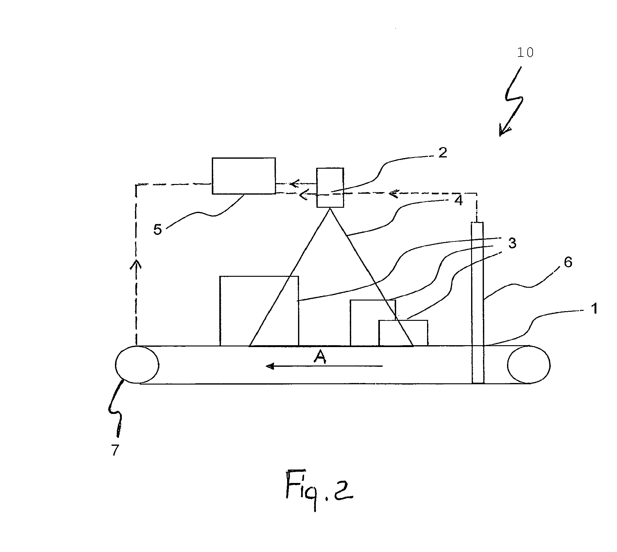
[0127]In FIG. 3, reference numeral 10 indicates an object identification system that carries out a first preferred embodiment of the method of the present invention.

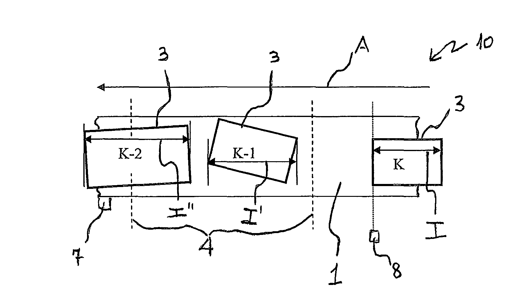
[0128]System 10 comprises a conveyor belt 1 which moves a plurality of objects 3 along an advancing direction A with respect to a digital camera 2, each object being provided with an optical code (not visible) on the top face thereof, such an optical code having a predetermined optical resolution.

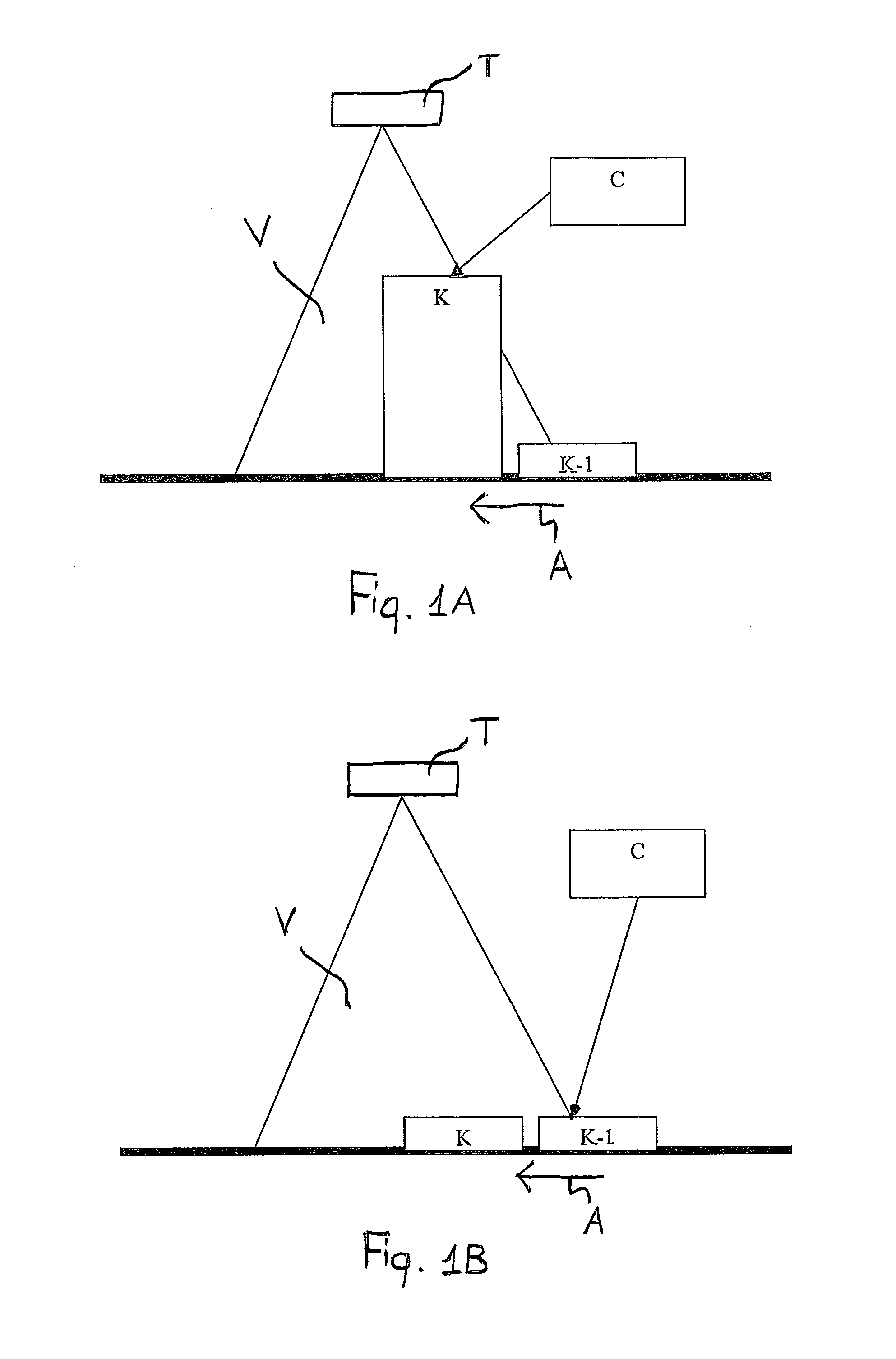
[0129]The camera 2 is arranged in a predetermined position with respect to the conveyor belt 1. In particular, it is arranged above the conveyor belt 1 and frames a detection area 4 shaped as a pyramid through which objects 3 travel.

[0130]Preferably, as shown, the camera 2 is arranged with its optical axis perpendicular to conveyor belt 1 and acquires images when objects 3 travel at said optical axis.

[0131]As shown, at least some of objects 3 are at least partly arranged side by side with reference to said advancing direction A....


PUM


Abstract

The method includes the steps of acquiring, by at least one camera having a predetermined magnification ratio, at least one image containing at least one coded information and at least one object and properly associating the coded information with the at least one object on the basis of the position of the coded information and of the at least one object along an advancing direction with respect to a fixed reference system. The above-mentioned position of the coded information is determined starting from the position of the coded information within the image acquired by the camera and on the basis of the distance of the coded information from the camera. Such a distance is in turn determined on the basis of the magnification factor of a reference physical dimension detected at a surface of the object or of the coded information.

Description

BACKGROUND AND SUMMARY OF THE INVENTION[0001]The present invention relates to a method for the optical identification of objects in motion.[0002]Throughout the following description and the following claims, the expression: “optical identification” is used to indicate the acquisition and reading of coded information of an object (for example distance, volume, overall dimensions, or object identification data) for example through the acquisition and processing of a light signal diffused by the same object. The term: “coded information” is preferably used to indicate the whole identification data contained in an optical code. The term: “optical code” is used to indicate any graphical representation having the function of storing said coded information.[0003]A particular example of optical code consists of the linear or two-dimensional codes, wherein the information is coded through suitable combinations of elements with a predetermined shape, for example squared, rectangular or hexago...

Claims


Application Information

Patent Timeline
IPC IPC(8): G06K9/00G06K7/10
CPCG06K9/00624G06K7/10861
Inventor FIORINI, DANIELEOWEN, RICKY DARRELLPELLEGRINO, LUIGI
Owner DATALOGIC IP TECH
Why Eureka
Try Eureka