
Method and apparatus for multiplexed fabry-perot spectroscopy

Active Publication Date: 2015-09-10
THE UNITED STATES OF AMERICA AS REPRESENTED BY THE SECRETARY OF THE NAVY
View PDF4 Cites 8 Cited by
  • Summary
  • Abstract
  • Description
  • Claims
  • Application Information

AI Technical Summary

Benefits of technology

The invention is a new method of optical spectroscopy that uses a low-computational burden transform to recover optical spectra from Fabry-Perot interferometers and arrays of Fabry-Perot etalons. This method can measure continuous spectra or discrete spectral components calculated using multiplexed Fabry-Perot signals. It allows for spectral measurement over the entire bandwidth of the detector while minimizing the effects of noise. The spectral resolution is not directly dependent on the step heights, making it more decoupled from the precision of the manufacture than in prior art devices. The method has several key advantages, including an improvement in spectral resolution relative to Fourier Transform processing techniques, an increase in fringe contrast relative to micro-optic devices with effective two-beam interference, disambiguation of Fabry-Perot transmission signals that have components separated by more than one free- spectral range of the maximum cavity retardation, measurement of optical signals over the entire bandwidth of the detector, and tuning or designing the cavity finesse to optimize the recovered spectral resolution and maximum frequency for a particular signal-to-noise condition.

Problems solved by technology

All of these spectral measurement methods have been applied to imaging systems, but none has achieved a compact device with acceptable broadband performance.
Drawbacks of using dispersive elements and Michelson interferometers are the space required to spread the spectrum across several elements of a detector and the size and weight of dispersive elements, beamsplitters and their mechanical mounts.
The primary disadvantage of using macroscopic size optical filters is related to size and weight.
These have been used in imaging devices, but with limited spatial and spectral resolution.
There is an unfavorable tradeoff space for using mosaic array filters for imaging spectroscopy.
The efficiency / resolution tradeoff available with optical filters also offers design challenges.
Similarly, lens-mounted optical filter arrays lead to the same disadvantageous tradeoff between spatial and spectral resolution.
Low reflectance leads to low fringe contrast in the measured interference pattern, leading to poor signal-to-noise ratio performance under typical field conditions.
An additional limitation of this device is that the Fourier Transform processing has a defined resolution that is tied directly to the maximum thickness of the wedged micro-optic.
Therefore, for any device thickness, the number of resolved spectral elements within the bandwidth of the detector is fixed and cannot be adjusted.
Second, in the case where the micro-optic device used high reflectance, good results have been obtained only over a limited bandwidth.
The spectral range of these devices is therefore limited to a single free-spectral range (“FSR”) of the etalons.
The spectral resolution of these devices is limited by the etalon finesse and the manufacturing tolerances for etalon arrays.
This type of device is difficult to manufacture, as step height must be accurately controlled, as each step is meant to provide unique information that is not duplicated by any other step.
Further, the allowed usable step heights are limited to a few hundred nanometers, as in order to only be resonant with one optical frequency within the allowed bandwidth, the devices must have a FSR greater than the allowed bandwidth.
This is due to the ambiguity between signals arising from colors separated by one FSR for any Fabry-Perot interferometer.
Fabry-Perot theory is only valid within one FSR, and is not capable of demultiplexing mixed signals.

Method used


Image

  • Method and apparatus for multiplexed fabry-perot spectroscopy
  • Method and apparatus for multiplexed fabry-perot spectroscopy
  • Method and apparatus for multiplexed fabry-perot spectroscopy

Examples


Embodiment Construction

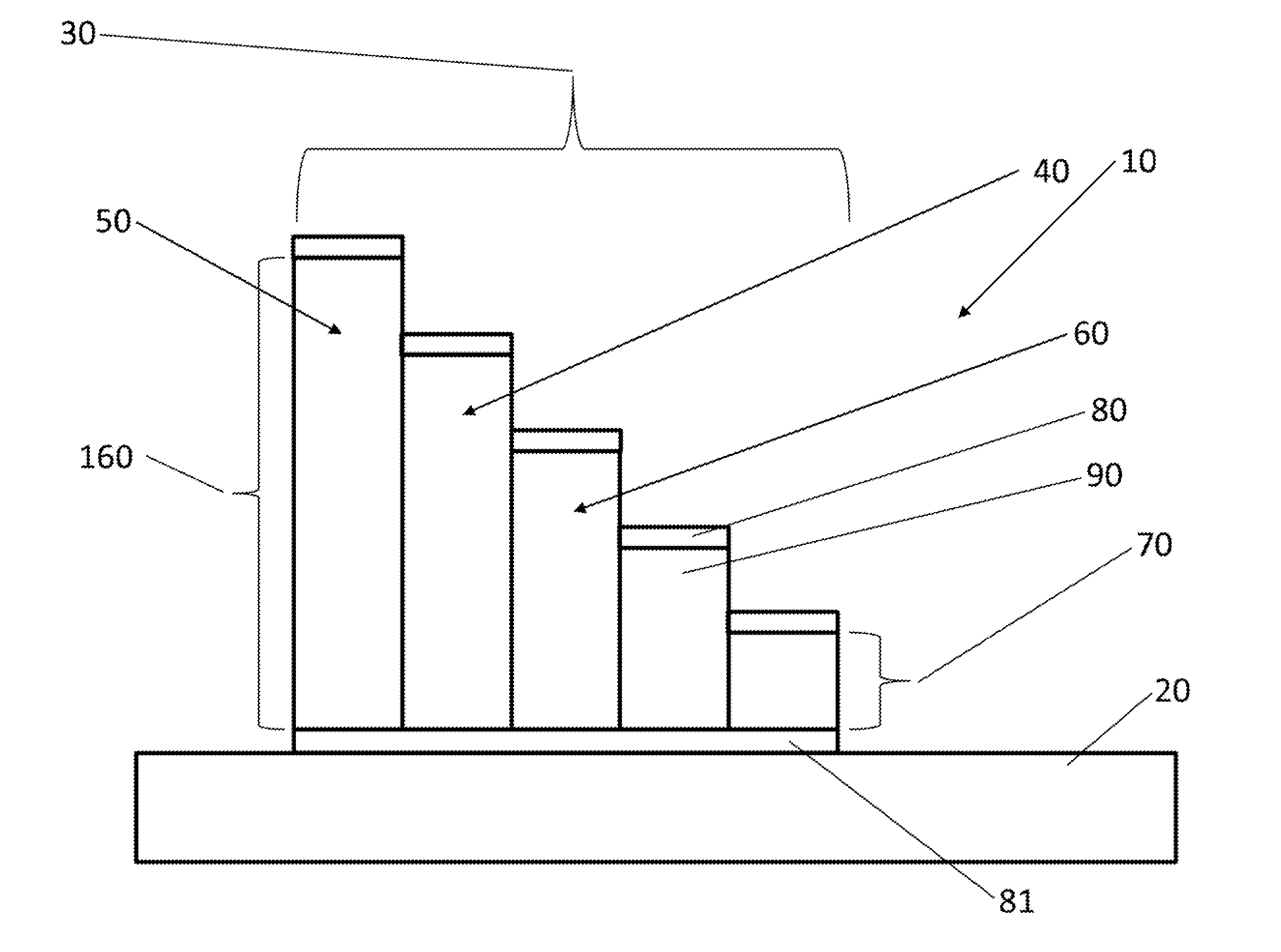
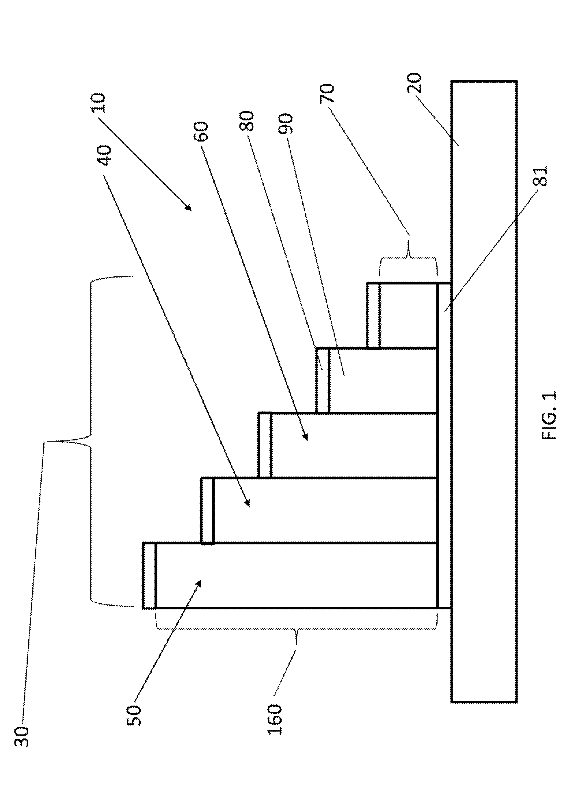
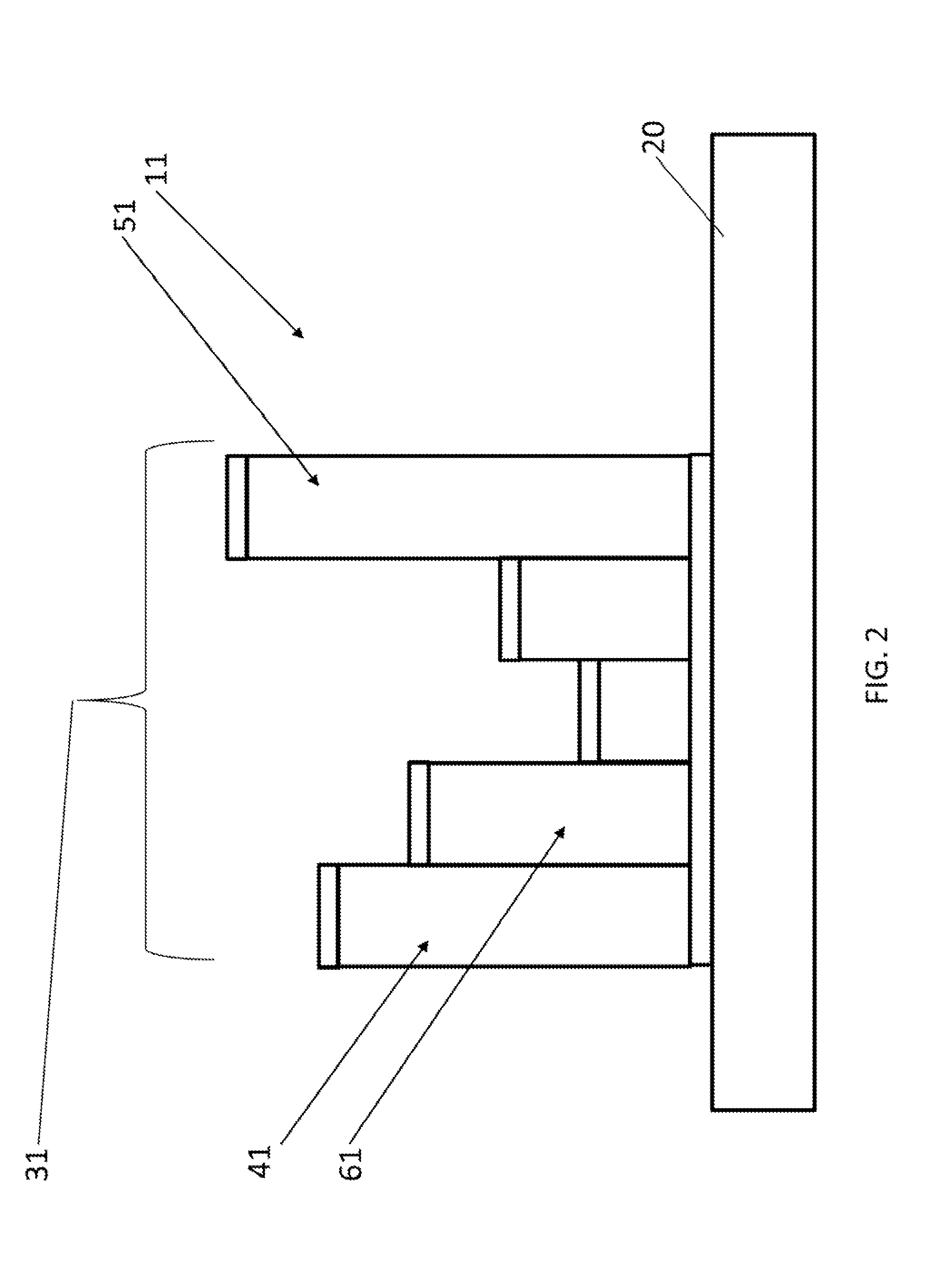
[0030]An embodiment of the invention includes a device 10, 11, and is described as follows by way of illustrative reference to FIGS. 1 and 2. The device 10, 11 includes a standard substrate 20 and a plurality of etalon cavities 30, 31 affixed to or coupled to the substrate. Although FIGS. 1 and 2 show the plurality of etalon cavities connected to the substrate, one of ordinary skill in the art will readily appreciate that an alternative embodiment includes the plurality of etalon cavities being operably coupled to the substrate, though not physically connected thereto. The plurality of etalon cavities 30, 31 include a plurality of cavity thicknesses. Each etalon cavity 40, 41 of said plurality of etalon cavities comprises a respective height value, said each etalon cavity of the plurality of etalon cavities has an associated next highest height value etalon cavity 50, 51 of the plurality of etalon cavities. The associated next highest height value etalon cavity of the plurality of e...


PUM


Abstract

A method of optical spectroscopy and a device for use in optical spectroscopy. The device includes a substrate, and a plurality of etalon cavities affixed to or coupled to the substrate. A signal is received from a Fabry-Perot interferometer. The signal is sampled using the device according to a generalized Nyquist-Shannon sampling criterion. The signal is sampled using the device according to a phase differential criterion for wave number resolution. An input spectrum for the signal is reconstructed based on the signal sampled according to the generalized Nyquist-Shannon sampling criterion and the signal sampled according to the phase differential criterion for wave number resolution.

Description

CROSS-REFERENCE TO RELATED APPLICATIONS[0001]This application claims priority to U.S. Provisional Patent Application Ser. No. 61 / 825,577, entitled “ALGORITHM AND APPARATUS AND DEVICE PARAMETERS FOR MULTIPLEXED FABRY-PEROT SPECTROSCOPY,” to Yetzbacher et al., which was filed on 21 May 2013 and is incorporated herein by reference.BACKGROUND OF THE INVENTION[0002]1. Field of the Invention[0003]This invention relates in general to method of optical spectroscopy and a device for use in optical spectroscopy, and in particular to method of optical spectroscopy capable of robustly recovering an optical spectrum or spectra associated with a scene using Fabry-Perot transmission data and a device for use in such optical spectroscopy.[0004]2. Description of the Related Art[0005]Several standard methods to measure spectra exist, using dispersive elements, interferometers, optical filters, and / or micro-optical components and associated transforms. All of these spectral measurement methods have be...

Claims


Application Information

Patent Timeline
IPC IPC(8): G01J3/26G01N21/45
CPCG01N21/45G01J3/26G01J3/021G01J3/45G01N21/41
Inventor YETZBACHER, MICHAEL K.MILLER, CHRISTOPHER W.DEPRENGER, MICHAEL J.BOUDREAU, ANDREW J.
Owner THE UNITED STATES OF AMERICA AS REPRESENTED BY THE SECRETARY OF THE NAVY
Learn More