
Systems and method for optical scatter imaging of latent image plates

a technology of optical scatter and optical scatter, applied in the field of systems and methods for optical scatter imaging of latent image plates, can solve the problems of ineffective process-free plate detection and analysis methods, traditional methods for targeting and analyzing printing plates, e.g., measuring dot coverage, etc., and achieve the effect of minimizing distortion and blurring effects

Inactive Publication Date: 2009-10-01
X RITE INC
View PDF7 Cites 4 Cited by
  • Summary
  • Abstract
  • Description
  • Claims
  • Application Information

AI Technical Summary

Benefits of technology

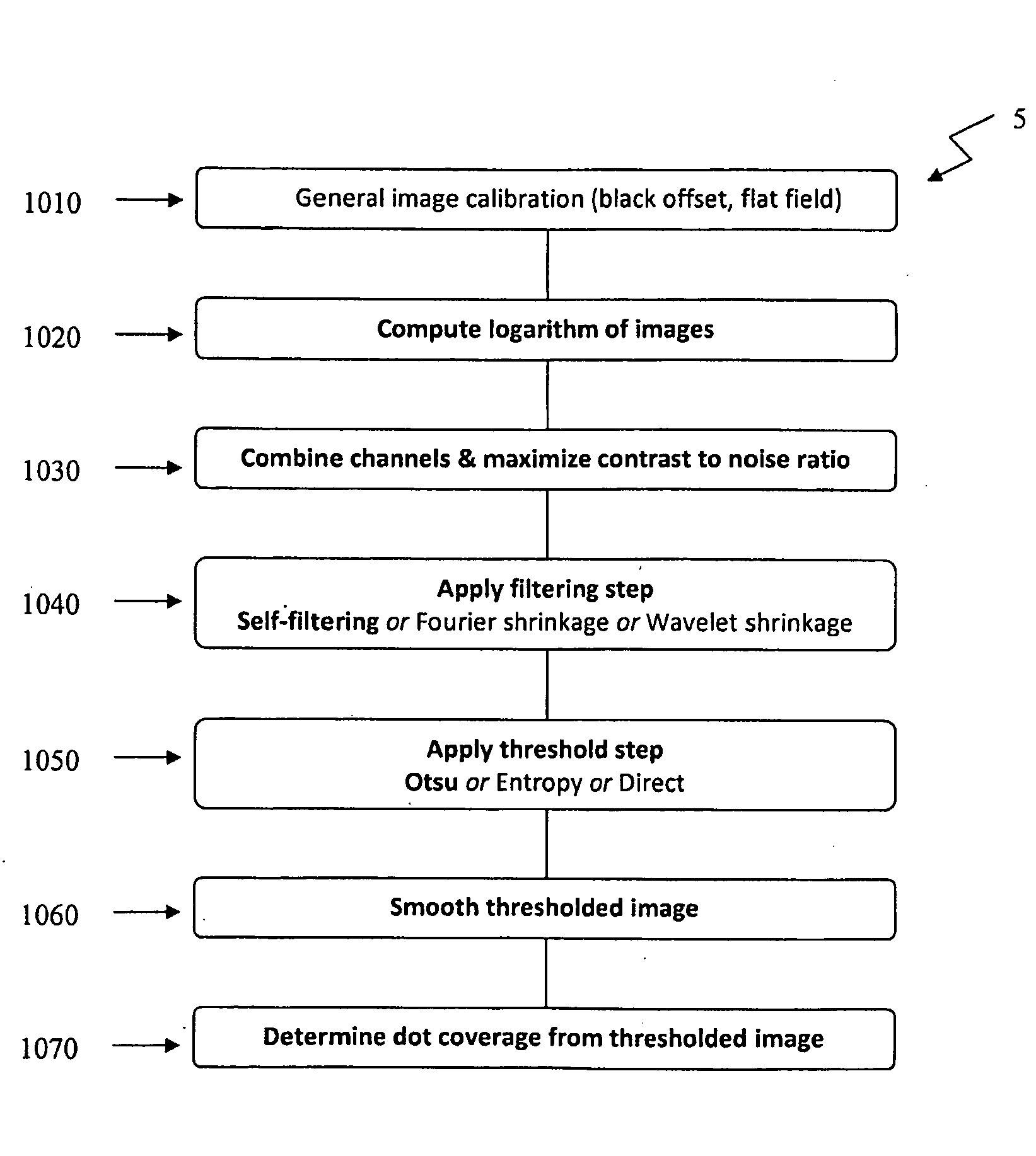
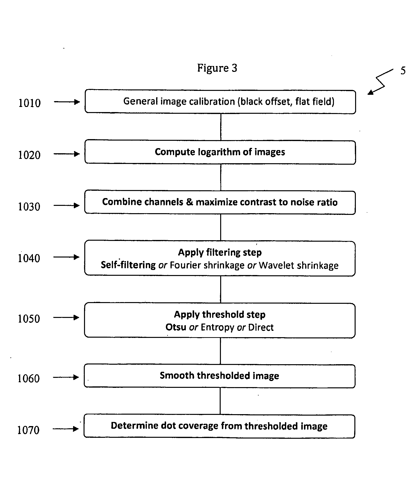
[0011]In exemplary embodiments the disclosed systems and methods may advantageously perform operations of image de-noising, contrast enhancement and thresholding. In addition, the disclosed systems and methods may employ compensation technique(s), e.g., for minimizing distortion and blurring effects.

Problems solved by technology

As a result, traditional methods for targeting and analyzing printing plates, e.g., measuring dot coverage, are often ineffective with respect to process-free plates.
Although the variation in intensity within the homogeneous regions is due to properties of the plate itself, and not due to noise introduced by the imaging system of a measurement device, enhancement of the image to enable computing the dot coverage of process-free plates may still be viewed as an image de-noising problem.

Method used


Image

  • Systems and method for optical scatter imaging of latent image plates
  • Systems and method for optical scatter imaging of latent image plates
  • Systems and method for optical scatter imaging of latent image plates

Examples


Embodiment Construction

)

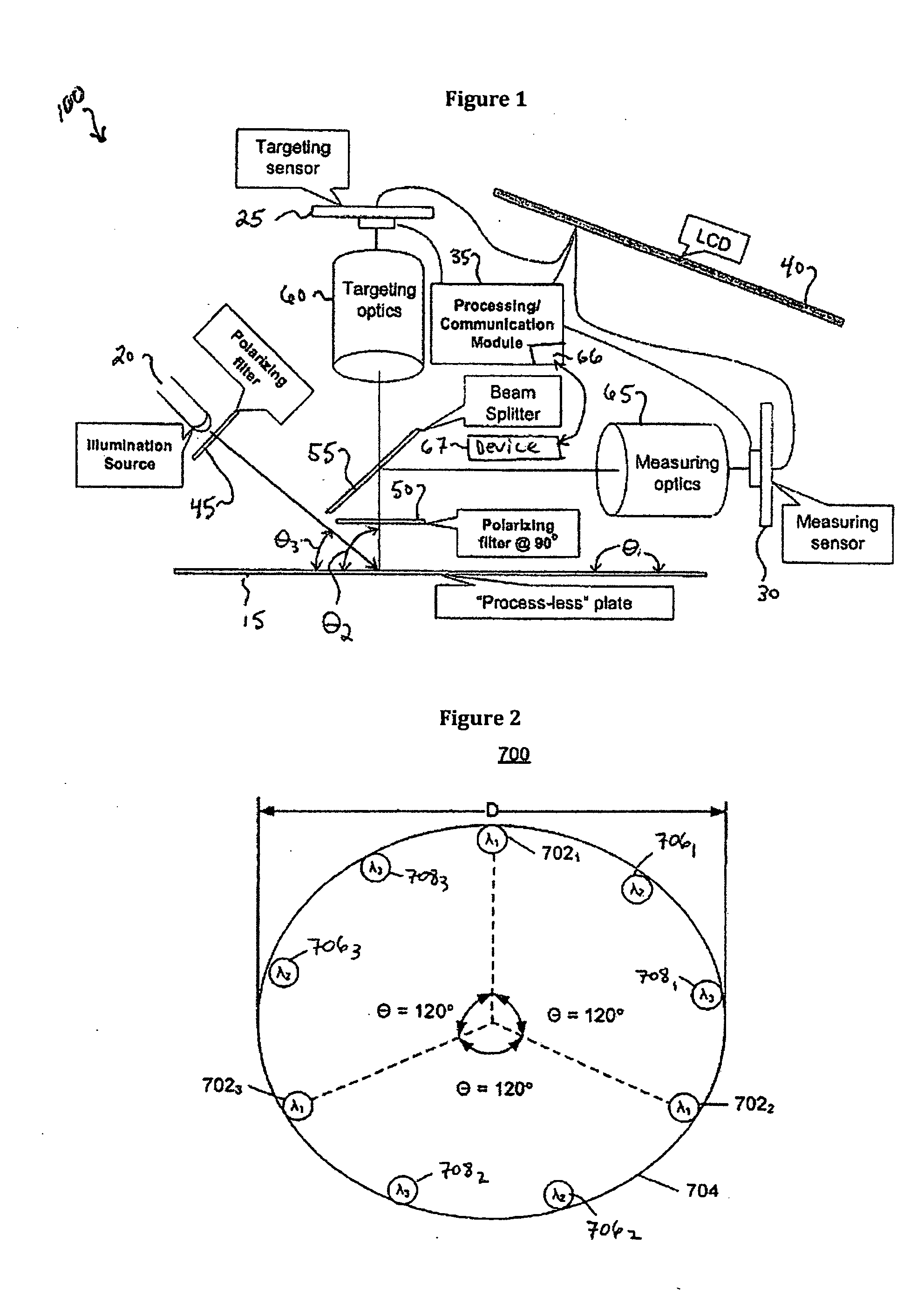
[0024]According to the present disclosure, advantageous systems and methods are provided for facilitating imaging of process-free plates.

[0025]For the purposes of this disclosure, a process-free plate may comprise, e.g., a substrate and one or more energy sensitive layers disposed relative to the substrate. Typically, the substrate is an aluminum sheet. However, the substrate may comprise any self-supporting material including but not limited to polymeric films, glass, ceramics, metals or paper or a lamination of any of these materials. The one or more energy sensitive layers of a process-free plate may advantageously respond to exposure at the predetermined wavelength to initiate crosslinking of the molecules thereof. Thus, in exemplary embodiments, an image may be formed on a process-free plate by exposing regions of the plate to the crosslinking wavelength. Although it is appreciated that the crosslinked regions may in various embodiments represent a positive or a negative of th...


PUM


Abstract

Computer-implemented systems and methods for processing image data of a process-free plate are provided according to the present disclosure. The systems and methods may, generally, include a data acquisition step / means for receiving image data using one or more channels of a imaging system, each channel functioning to image the same target region of a process-free plate using a different wavelength of light, and a data processing step / means for filtering the image data using at least one of: (i) self-filtering, (ii) Fourier shrinkage and (iii) Wavelet shrinkage. When the image data is received using a plurality of channels, the received image data may advantageously be combined so as to optimize contrast-to-noise performance. The disclosed systems and methods may advantageously perform the operations of image de-noising, contrast enhancement, and thresholding, and may further involve compensation techniques, e.g., for minimizing distortion and blurring effects.

Description

CROSS-REFERENCE TO RELATED APPLICATIONS[0001]The present application is a Continuation-in-Part (CIP) of co-pending, commonly assigned non-provisional U.S. patent application Ser. No. 11 / 517,911 entitled “DEVICES AND METHODS FOR TARGETING PRINTING PLATES AND MEASURING DOT COVERAGE THEREON,” filed on Sep. 8, 2006, which, in turn, claims priority to U.S. Patent Application No. 60 / 715,117 entitled “METHOD OF TARGETING AND READING DOT COVERAGE ON ‘PROCESSLESS’ AND ‘SEMI-LATENT IMAGE’ CTP PRINTING PLATES,” filed Sep. 8, 2005, and to U.S. Patent Application No. 60 / 788,899 entitled “DEVICES AND METHODS FOR TARGETING PRINTING PLATES AND MEASURING DOT COVERAGE THEREON,” filed Apr. 3, 2006. The entire contents of the foregoing non-provisional and provisional patent application are incorporated herein by reference.BACKGROUND[0002]1. Technical Field[0003]The present disclosure relates to systems and methods for targeting and analyzing an area of a process-free plate, e.g., for reading dot covera...

Claims


Application Information

Patent Timeline
Patent Type & Authority Applications(United States)
IPC IPC(8): H04N1/409G06F3/12
CPCB41C1/1083G06T5/50G06T2207/20148G06T2207/20192G06T5/009G06T2207/20036G06T5/002G06T7/136G06T5/92G06T5/70
Inventor NISPER, JON KENNETHWEBER, MICHAEL J.RICHARDSON, THOMAS M.
Owner X RITE INC
Learn More