Fuel cell system and operation method therefor

a fuel cell and system technology, applied in the direction of electric energy management, electric device, driver interaction, etc., can solve the problems of fuel cell system cease operation, cells become inability to sustain power generation, depletion of secondary battery charge, etc., to achieve the effect of maintaining convenien

Inactive Publication Date: 2007-11-29
YAMAHA MOTOR CO LTD
View PDF8 Cites 11 Cited by
  • Summary
  • Abstract
  • Description
  • Claims
  • Application Information

AI Technical Summary

Benefits of technology

[0007]In order to overcome the problems described above, preferred embodiments of the present invention provide a fuel cell system and operation method therefor capable of ensuring transfer to normal operation while maintaining convenience.

Problems solved by technology

However, since it is possible to abort charging after the operation stop command is issued, the technique according to Patent Document 1 poses a risk that the amount of charge stored in the secondary battery will be depleted in the next cycle of operation, before the fuel cell's output covers the system's power consumption.
This means that the fuel cells become unable to sustain power generation, and the fuel cell system ceases its operation before entering into normal operation.

Method used


Image

  • Fuel cell system and operation method therefor
  • Fuel cell system and operation method therefor
  • Fuel cell system and operation method therefor

Examples


Embodiment Construction

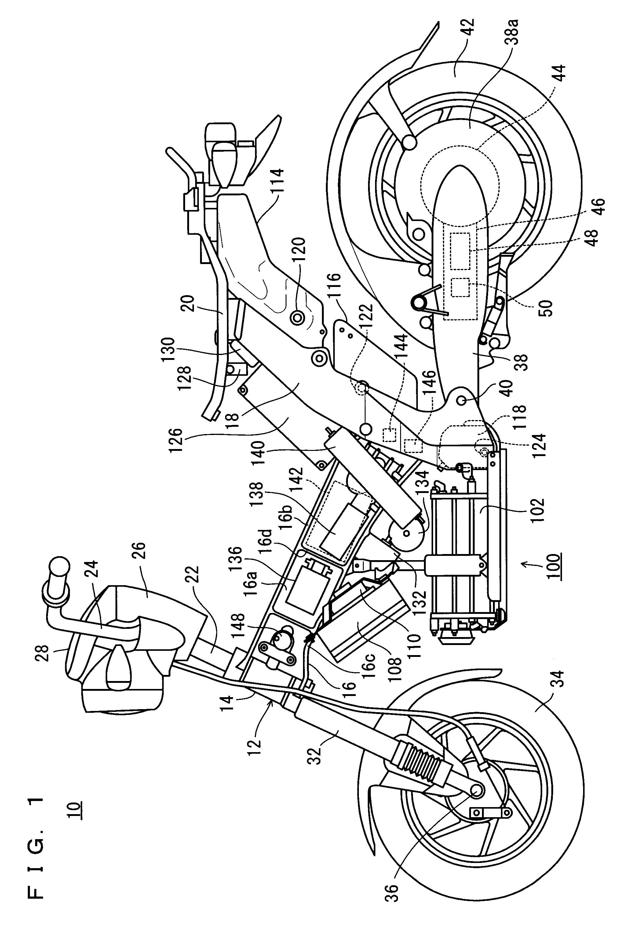
[0030]Hereinafter, preferred embodiments of the present invention will be described, with reference to the drawings. The preferred embodiments are cases in which a fuel cell system 100 according to the present invention is equipped in a motorbike 10 as an example of transportation equipment.

[0031]The description will first cover the motorbike 10. It is noted that the terms left and right, front and rear, up and down as used in the preferred embodiments of the present invention are determined from the normal state of riding, i.e., as viewed by the driver sitting on the driver's seat of the motorbike 10, with the driver facing toward a handle 24.

[0032]Referring to FIG. 1, the motorbike 10 includes a vehicle frame 12. The vehicle frame 12 has a head pipe 14, a front frame 16 which has an I-shaped vertical section and extends in a rearward and downward direction from the head pipe 14, a rear frame 18 which is connected with a rear end of the front frame 16 and rising in a rearward and u...


PUM

PropertyMeasurementUnit
temperatureaaaaaaaaaa
temperaturesaaaaaaaaaa
power tapping temperatureaaaaaaaaaa

Abstract

A fuel cell system and operation methods therefore are capable of ensuring transfer to normal operation while maintaining convenience. A fuel cell system includes a cell stack, a secondary battery, and a controller including a CPU, a main switch, and a stop button. After the main switch is turned OFF, if there is no power generation stopping command from the stop button, the CPU stops power generation in the cell stack after continuing power generation in the cell stack until a charge rate of the secondary battery becomes not lower than a first threshold value. If the charge rate is not lower than a second threshold value and is lower than the first threshold value, generation in the cell stack is stopped in response to the power generation stopping command from the stop button. If the charge rate is lower than the second threshold value, power generation in the cell stack is continued to charge the secondary battery until the charge rate becomes not lower than the second threshold value even if a normal power generation stopping command is provided from the stop button.

Description

BACKGROUND OF THE INVENTION[0001]1. Field of the Invention[0002]The present invention relates to fuel cell systems and operation methods therefor. More specifically, the present invention relates to fuel cell systems and operation methods therefor where power generation in the fuel cell is continued even after receiving an operation stop command, in order to charge a secondary battery if the secondary battery has not been charged to a predetermined extent.[0003]2. Description of the Related Art[0004]Fuel cell systems mounted on transportation equipment and electronic apparatuses make use of a secondary battery for driving system components in order to start power generation in the fuel cells. In these fuel cell systems, it is a common practice to continue power generating operation in the fuel cells even after receiving an operation stop command if the secondary battery has not been charged to a predetermined threshold. By charging the secondary batteries in this way, these systems ...

Claims


Application Information

Patent Timeline
Patent Type & Authority Applications(United States)
IPC IPC(8): H01M16/00H01M8/04H01M10/46
CPCH01M8/04201Y02T10/7291H01M8/0494H01M8/1011H01M16/003H01M2250/20B60L1/003B60L3/0053B60L11/1805B60L11/1816B60L11/1885B60L11/1887B60L2200/12B60L2240/36B60L2240/662B60L2250/16Y02E60/50Y02T90/16Y02T90/34Y02T90/14Y02T90/32H01M8/04626B60L50/52B60L58/31B60L58/32B60L58/40Y02T10/70Y02T10/72Y02T90/40Y02T10/7072
Inventor MURAMATSU, YASUYUKI
Owner YAMAHA MOTOR CO LTD
Why Eureka
Try Eureka