Orthodontic force module

a force module and orthodontic technology, applied in the field of orthodontics, can solve the problems of force module and easy breakage of tempered leaf spring locking mechanism, and achieve the effect of less sensitive to mechanical breakage and more protection

Inactive Publication Date: 2007-11-29
HANKS STEPHEN D
View PDF23 Cites 20 Cited by
  • Summary
  • Abstract
  • Description
  • Claims
  • Application Information

AI Technical Summary

Benefits of technology

[0008] In a preferred embodiment, the lock mechanism according to the invention comprises a housing having an outwardly opening recess and a bearing surface in engagement with the jack screw. The spring is disposed in the recess and confined for compression between the detent and the housing. A guide rod is slidably disposed in guide openings in each of the nut housings, and the housing of the lock mechanism is secured to the guide rod such that the lock mechanism does not rotate relative to the jack screw when the jack screw is rotated in a manner effective to cause the nut housings to move toward or away from one another. For this purpose, the housing of the lock mechanism can be slidably supported on the guide rod, or the guide rod can be made integral with the housing, e.g. as projections extending in opposite directions. A pair of attachment rods extend from each of the nut housings, which attachment rods are configured for attachment to an orthodontic appliance to be installed in the mouth of a patient.
[0009] In an especially preferred embodiment, the openings of each through hole in the spindle section are configured to receive a coil-spring activated detent element oriented perpendicularly to the long axis of the jack screw either within the confines of a lock housing, thereby “locking” and “unlocking” according to compression or expansion of the encapsulated coil spring. The detent element / lock housing interface with lock-seats of the spindle section inhibit the spindle from spontaneously rotating in a direction that would decrease the magnitude of desired force, but that, in fact, will readily without adjunct tooling or instruction allow reverse rotation of the spindle according to the need and desire of the prescribing clinician. A force module such as described in Huge et al. provided with a tempered leaf spring locking mechanism is prone to breakage as a result of binding with the plurality of activating tools. In the “RatchetRax” device, if after partial activation and bowing of the leaf spring, the direction is reversed against the “bow” of the spring, a binding force can occur thereby causing the leaf spring to break. A sliding ball or cup locking arrangement of the present invention is activated by a coil spring as opposed to a leaf spring, which coil spring is protected from all outside destructive influences by virtue of its encapsulation within the confines of the lock housing thereby rendering it more protected and hence less sensitive to mechanical breakage. Furthermore, the nature of a coil spring as it functions through a cycle of expansion and contraction is not stressed and therefore not prone to break like a “bowed” leaf spring is if in mid-cycle the direction of stress is reversed.

Problems solved by technology

A force module such as described in Huge et al. provided with a tempered leaf spring locking mechanism is prone to breakage as a result of binding with the plurality of activating tools.

Method used


Image

  • Orthodontic force module
  • Orthodontic force module
  • Orthodontic force module

Examples


Embodiment Construction

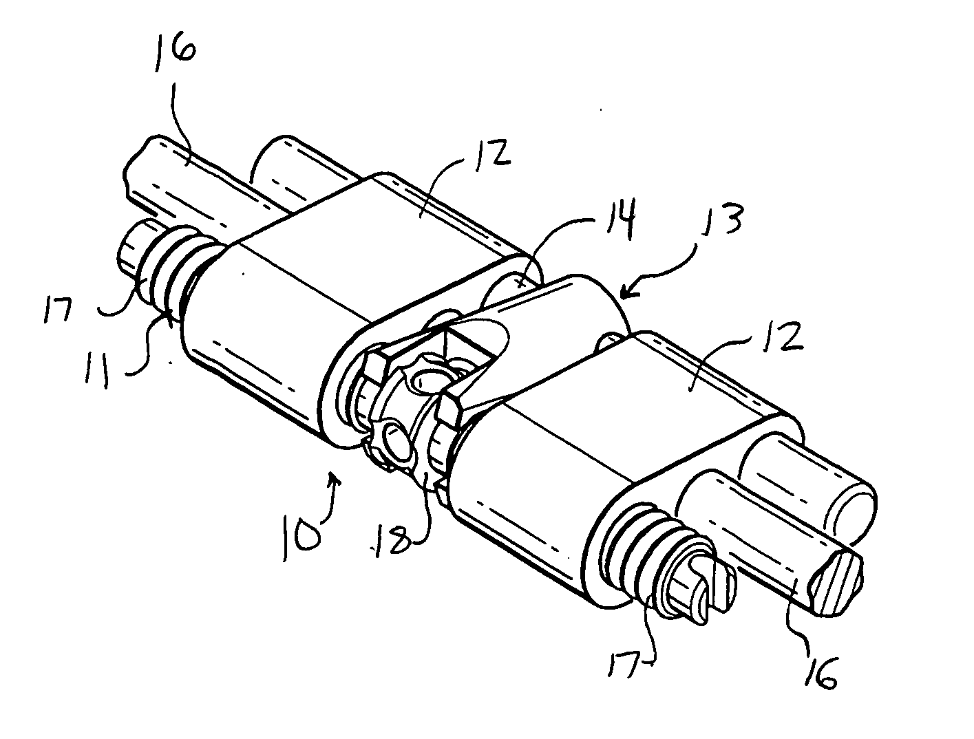
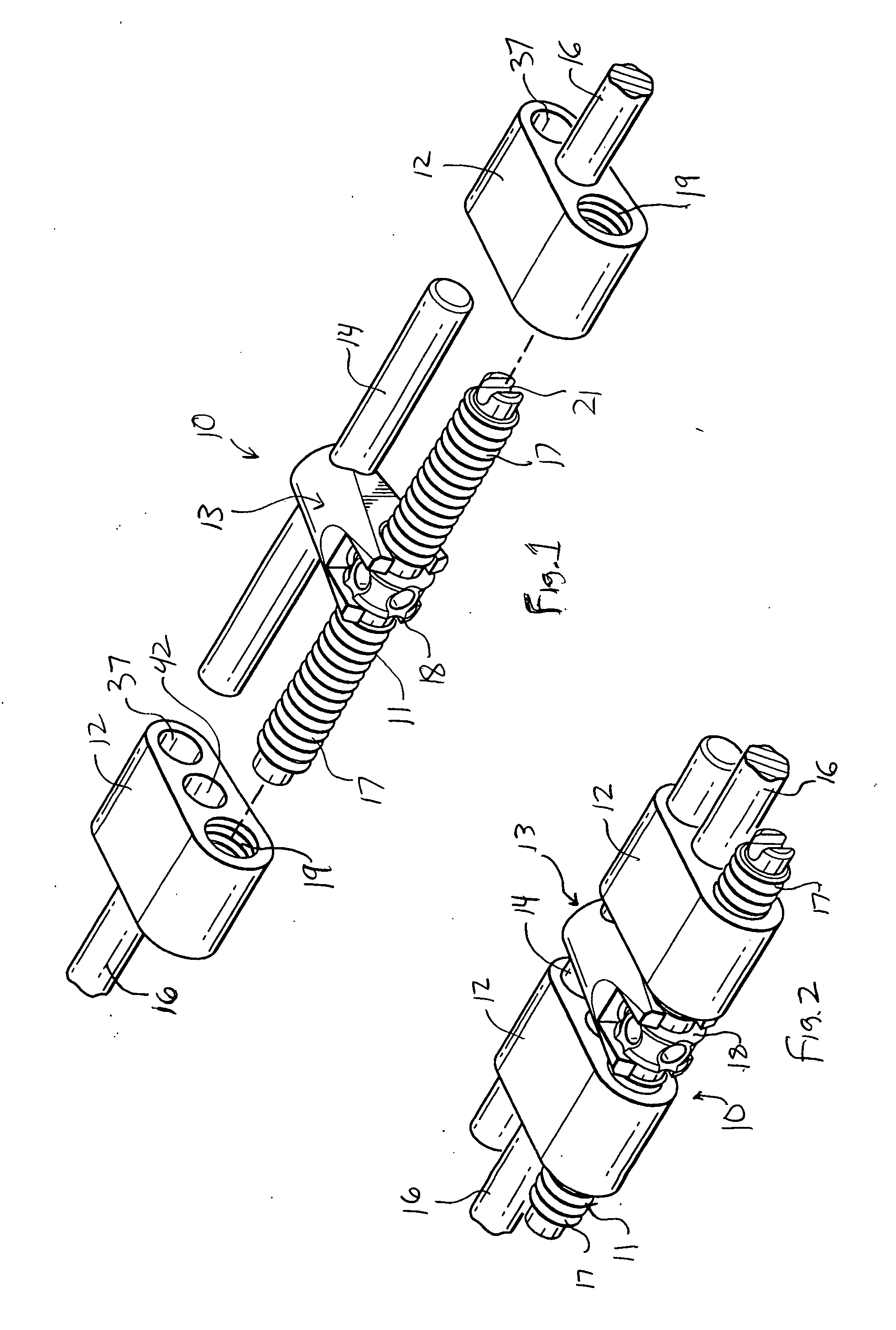
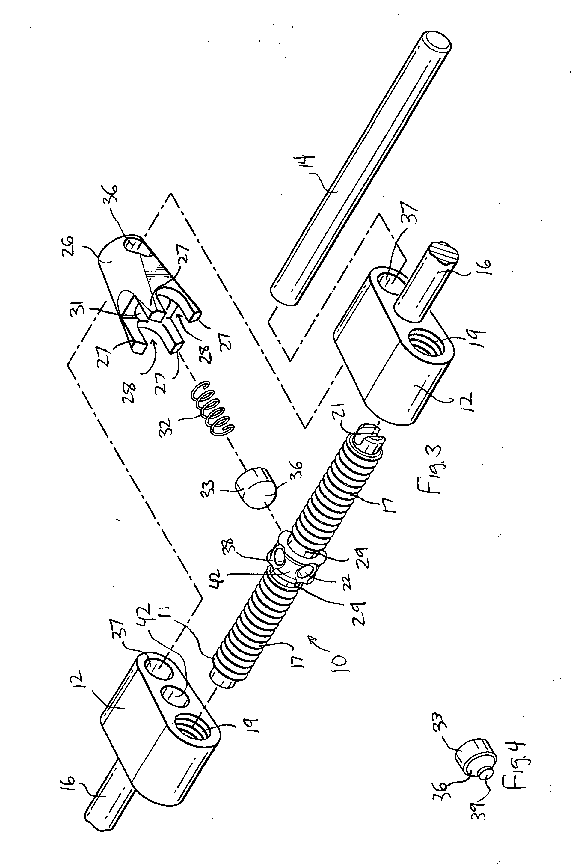
[0018] The force module according to the invention has two main applications. In a first application, the nut housings are as proximate as possible and the desired result is to create a wider separation of anatomical entities, e.g., rapid palatal expansion. The main body of the device in its closed state is centered over the midline of a patient's palate with a clearance of some few millimeters with the lateral rods connected at their distal ends either by welding, brazing, or some other mechanical interface to the lingual surface of “bands” (braces) on a single tooth or multiple teeth on each side of the jaw. The end result of the expansion protocol is to open the suture joint which runs in the midline of the palate thereby separating one side from the other thus creating a greater inter-dimensional width between the teeth supporting the device. Activation is achieved by progressively rotating the jack screw in a direction to cause the device body or bodies to move apart from each ...


PUM


Abstract

An orthodontic force mechanism according to the invention includes an elongated jack screw having at a pair of end portions, at least one of which is threaded, and a central spindle section between the end portions, which spindle section has at least two intersecting radial through-holes therein. A pair of nut housings are mounted on the end portions of the jack screw, at least one of which is threadedly coupled to a threaded end portion of the jack screw. A lock mechanism is mounted on the central spindle section, which lock mechanism includes a spring-loaded detent configured to engage an end opening of each of the through holes in the spindle section when such through hole is in alignment with the detent, such that the spindle cannot rotate relative to the lock mechanism when the detent is inserted into a through-hole, and is free to rotate relative to the lock mechanism when the detent is clear of a through hole. The detent can be moved out of engagement with a through hole using a tool inserted into that through hole from its opposite end, such that a distal end of the tool pushes the detent out of the through-hole, and the same tool can then be used to rotate the jack screw.

Description

FIELD OF THE INVENTION [0001] The present invention generally relates to orthodontics and, more particularly, to an orthodontic force modules of the type used for palatal expansion and other applications. BACKGROUND OF THE INVENTION [0002] Orthodontic palatal expansion is commonly carried out using a force module that is installed on the upper dental arch of a patient's mouth, the force module being connected to a palatal expander of a type commonly known in the art. The method of palatal expansion using expansion screws has become known in the art as “rapid palatal expansion” (RPE). Force modules used for this purpose must be tightened periodically to be effective. [0003] Huge et al. U.S. Pat. No. 6,783,361, Aug. 31, 2004, describes an orthodontic mechanical force module having a jack screw whose rotation is controlled by a ratchet. In one embodiment, a pair of housings are interconnected with the patient in any appropriate manner, and are further rotatably interconnected with a ro...

Claims


Application Information

Patent Timeline
Patent Type & Authority Applications(United States)
IPC IPC(8): A61C3/00
CPCA61C7/10
Inventor HANKS, STEPHEN D.
Owner HANKS STEPHEN D
Why Eureka
Try Eureka