Supercharge Your Innovation With Domain-Expert AI Agents!

Connector and mirror angle adjustment device

a technology of connecting device and mirror, which is applied in the direction of coupling device connection, transportation and packaging, instruments, etc., can solve the problems of cumbersome wire harness running, terminal is not readily pulled out of the terminal retaining socket, etc., and achieves the effect of improving assembly workability and increasing assembly workability

Inactive Publication Date: 2007-11-29
KK TOKAI RIKA DENKI SEISAKUSHO
View PDF9 Cites 1 Cited by
  • Summary
  • Abstract
  • Description
  • Claims
  • Application Information

AI Technical Summary

Benefits of technology

The present invention relates to a connector with a pull-out prevention configuration that improves workability and increases the efficiency of assembly. The connector includes a terminal that is securely retained in a housing and is prevented from coming out of the housing. The connector also includes a cover that is integrally connected to the housing and is resiliently deformable or plastically deformable, making it easy to align the cover to the mounting position. The invention also provides a guide portion that guides the cover to the mounting position and a lance that engages with the guide opening to prevent the terminal from coming out of the housing. These features make the connector more user-friendly and efficient in assembly.

Problems solved by technology

The running of the wire harness is cumbersome.
As a result, the terminal is not readily pulled out from the terminal retaining socket.

Method used


Image

  • Connector and mirror angle adjustment device
  • Connector and mirror angle adjustment device
  • Connector and mirror angle adjustment device

Examples


first exemplary embodiment

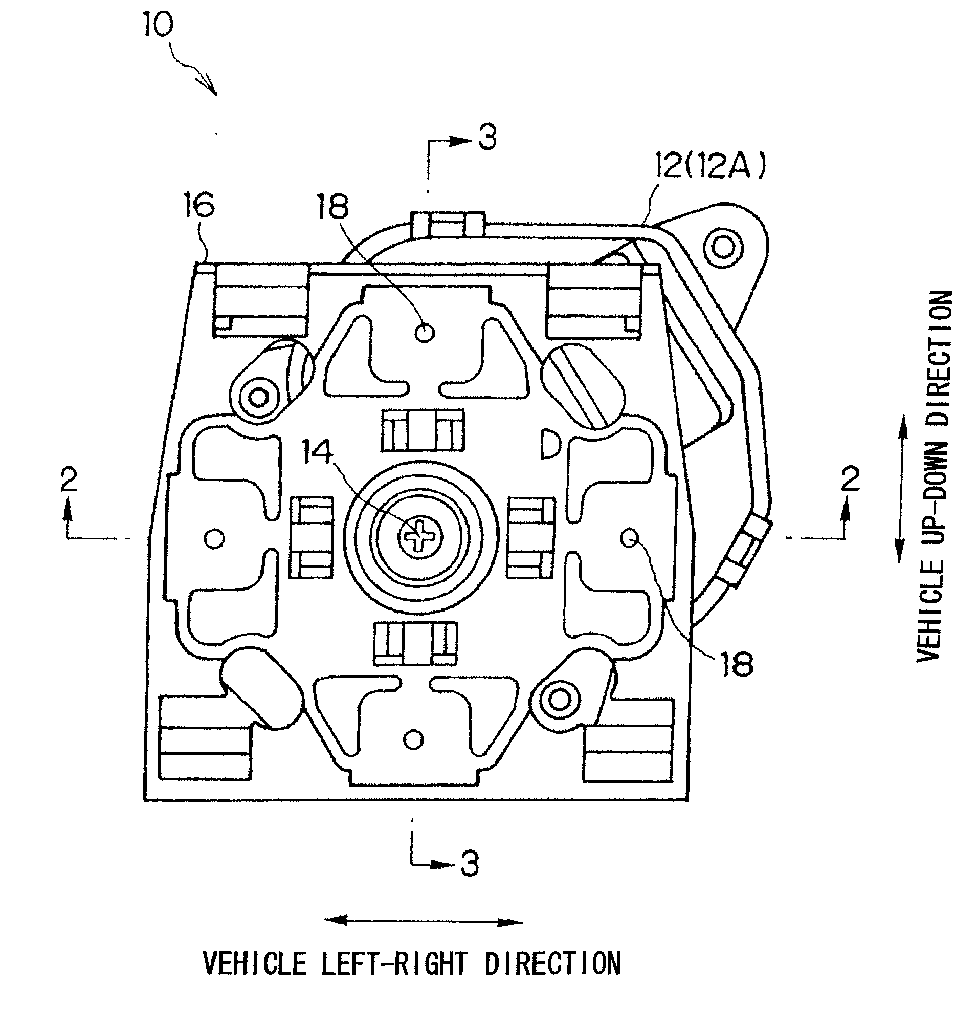
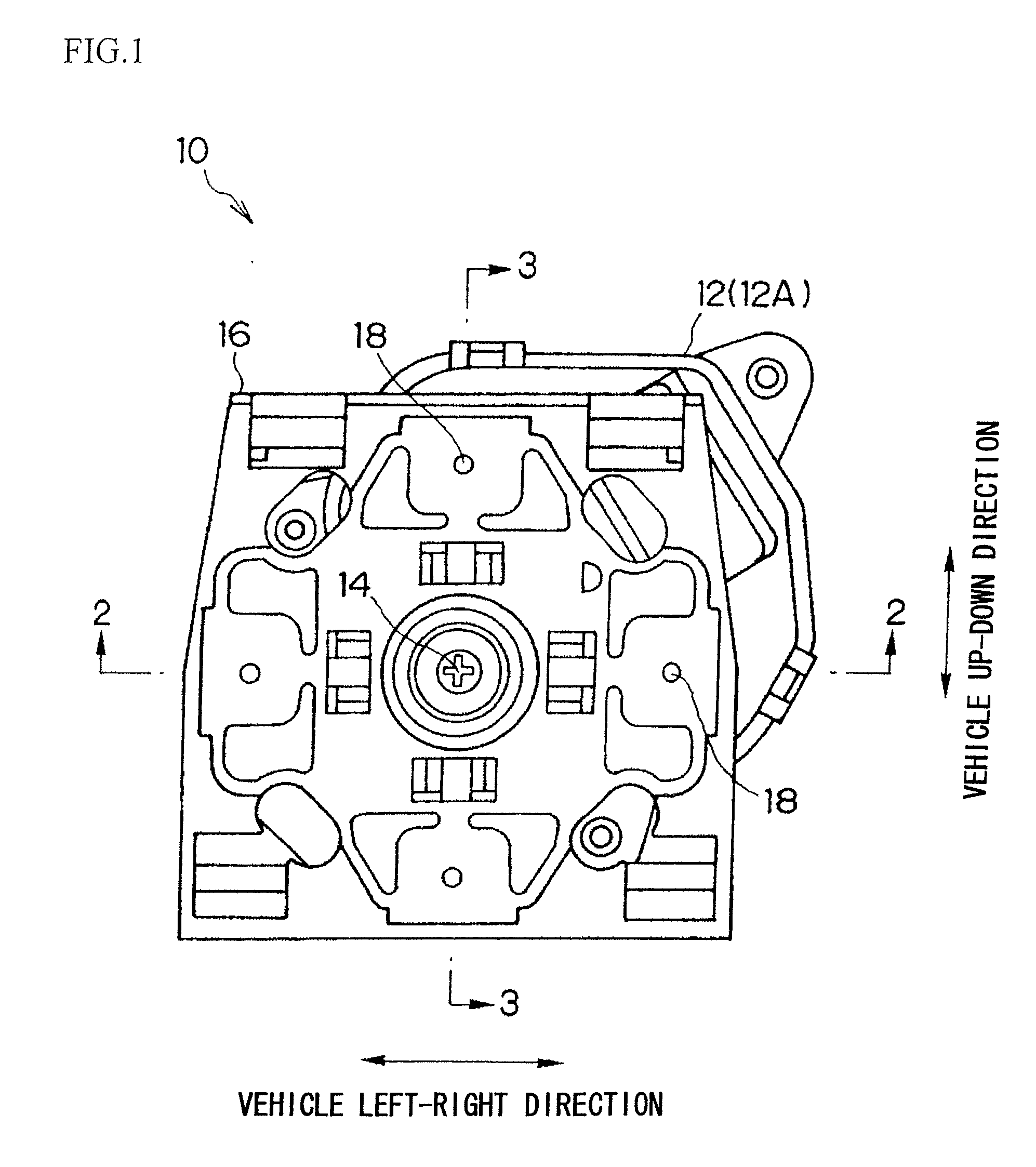
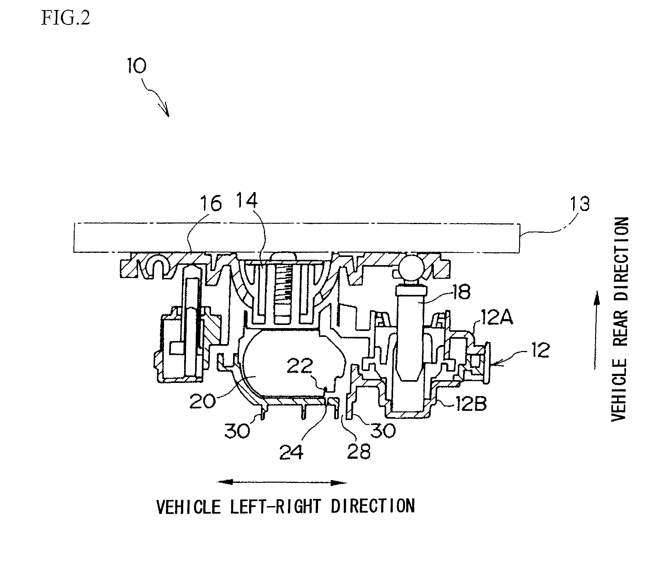
[0042]FIG. 1 is a front view of a mirror angle adjustment device 10 relating to a first exemplary embodiment and a second exemplary embodiment of the present invention. In addition, FIG. 2 shows a cross-section taken on 2-2 of FIG. 1, and FIG. 3 shows a cross-section taken on 3-3 of FIG. 1. Also, FIG. 4 shows a partial cut-away rear view of the mirror angle adjustment device 10.

[0043]The mirror angle adjustment device 10 of the present exemplary embodiment is provided with a case 12 as a body to be fitted to, and the case 12 is disposed at the back face side (vehicle rearward side) of a mirror body 13 for a vehicle rear-view mirror (see FIG. 2 and FIG. 3, omitted in FIG. 1 and FIG. 4). The case 12 is configured with a lower case 12A on the mirror body 13 side, and an upper case 12B on the side that is opposite to the mirror body 13. A retaining portion 14 is provided on the mirror body 13 side of the case 12 (lower case 12A), and a mirror holder inner 16 is swingably retained at the...

second exemplary embodiment

[0067]Next, a mirror angle adjustment device 10 relating to a second exemplary embodiment of the present invention will be explained. The mirror angle adjustment device 10 relating to the second exemplary embodiment of the present invention is one in which, for the connector 30, the shapes of the closure plate 32 and the cover 46 are changed. Below, those elements of the configuration similar to those of the above first exemplary embodiment will be allocated the same reference numerals, and explanation thereof will be omitted.

[0068]In the connector 30, as shown in FIG. 12 and FIG. 13, the closure plate 32 has a substantially rectangular hole shaped guide hole 52 as a guide portion. The guide hole 52 is at a central portion in the longitudinal direction of the closure plate 32, and formed on the inside of the surrounding wall 41 in the vicinity of the hinge portions 44 (in FIG. 12 and FIG. 13 on the cover 46 side). There is a sloping portion 52A, as a sloping part of the guide hole 5...


PUM


Abstract

A connector, comprising: a terminal that is an elongated member connected to a wire harness, the axial direction of the wire harness intersecting with the longitudinal direction of the terminal at a connecting portion therebetween; a housing, including a terminal retaining socket that retains the terminal, the terminal being inserted into the terminal retaining socket from a back face side of the housing and retained, with the leading end portion of the terminal protruding to a front face side of the housing, and the terminal being connected to a power supply point by the front face side of the housing being fitted together with a body to be fitted to; and a cover that is substantially plate shaped and covers the back face side of the housing, is provided.

Description

CROSS-REFERENCE TO RELATED APPLICATION [0001]This application claims priority under 35 U.S.C 119 from Japanese Patent Application No. 2006-143249, the disclosure of which is incorporated by reference herein.BACKGROUND[0002]1. Technical Field[0003]The present invention relates to a connector that is connected to a motor or the like, and a mirror angle adjustment device that adjusts the mirror angle of a mirror body for a vehicle rear-view mirror.[0004]2. Related Art[0005]There is a mirror angle adjustment device mounted to a mirror body for a vehicle rear-view mirror, for adjusting the mirror angle. Furthermore, in the mirror angle adjustment device, there are proposals for providing drive portions with motors and the like, and, in order to supply power to these drive portions, connectors are connected to the motors of the drive portions (see connectors of Japanese Patent No. 3345372).[0006]With the connector described in JP No. 3345372, there is a wire harness connected to a termina...

Claims


Application Information

Patent Timeline
Patent Type & Authority Applications(United States)
IPC IPC(8): H01R13/40
CPCB60R1/072
Inventor MORI, FUMIKATSUKATO, YOSHIAKI
Owner KK TOKAI RIKA DENKI SEISAKUSHO
Features
  • R&D
  • Intellectual Property
  • Life Sciences
  • Materials
  • Tech Scout
  • Unparalleled Data Quality
  • Higher Quality Content
  • 60% Fewer Hallucinations
Learn More