Endoscope, endoscopic apparatus, and examination method using endoscope

a technology of endoscope and endoscope, which is applied in the field of endoscope, endoscope, endoscopic apparatus, and examination method using endoscope, can solve the problems of difficult observation and too tiny capillary vessel observation

Active Publication Date: 2007-11-29
OLYMPUS CORP
View PDF14 Cites 55 Cited by
  • Summary
  • Abstract
  • Description
  • Claims
  • Application Information

AI Technical Summary

Benefits of technology

[0009]An endoscope of one embodiment of the present invention includes an insert section to be inserted into the body cavity, an illumination window for directing illumination light therethrough and an observation window for observing an illuminated internal portion of the body cavity, arranged at a distal end portion of the insert section, and a blood flow changing section for changing a blood flow of blood flowing through a vessel in a near-surface region of a living organ inside the body cavity by providing one of a temperature change and vibration energy.
[0010]An endoscopic apparatus of another embodiment of the present invention includes an endoscope including an insert section to be inserted into the body cavity, an illumination window for directing illumination light therethrough and an observation window for observing an illuminated internal portion of the body cavity, arranged at a distal end portion of the insert section, and a blood flow changing section for changing a blood flow of blood flowing through a vessel in a near-surface region of a living organ inside the body cavity by providing one of a temperature change and vibration energy, and a light source for supplying the illumination light to the endoscope.

Problems solved by technology

However, the capillary vessel is too tiny to observe.
More specifically, since the capillary vessel appears and disappears in synchronization with heart beat, it is difficult to observe it.

Method used


Image

  • Endoscope, endoscopic apparatus, and  examination method using endoscope
  • Endoscope, endoscopic apparatus, and  examination method using endoscope
  • Endoscope, endoscopic apparatus, and  examination method using endoscope

Examples


first embodiment

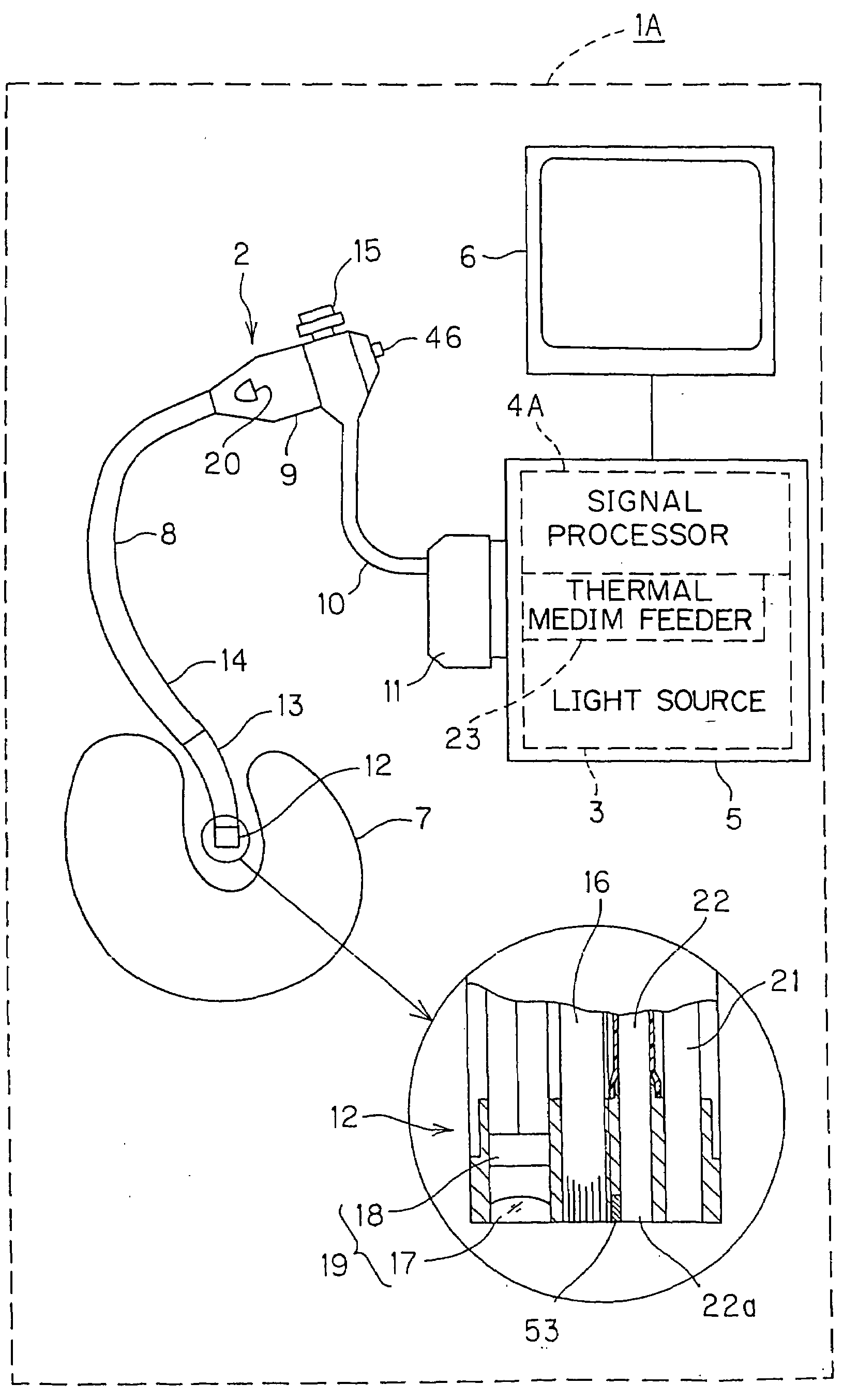
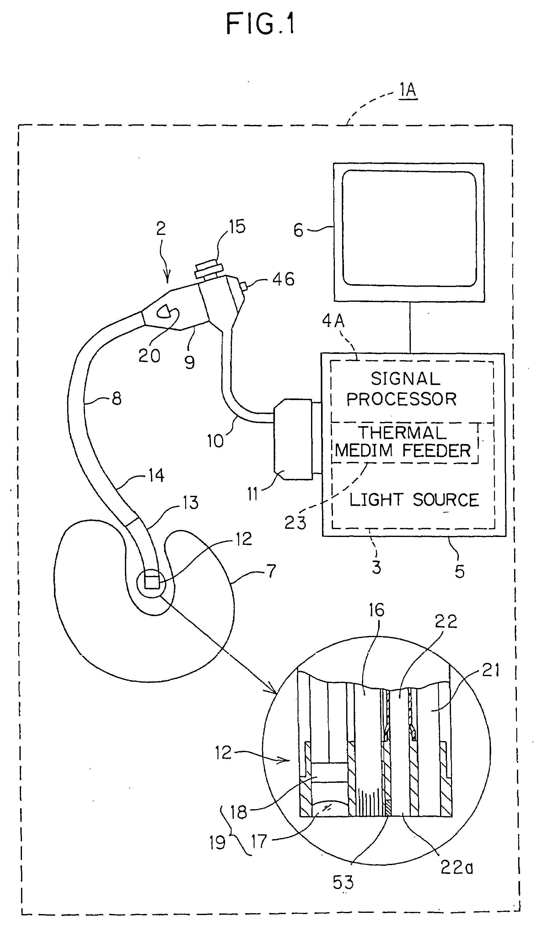
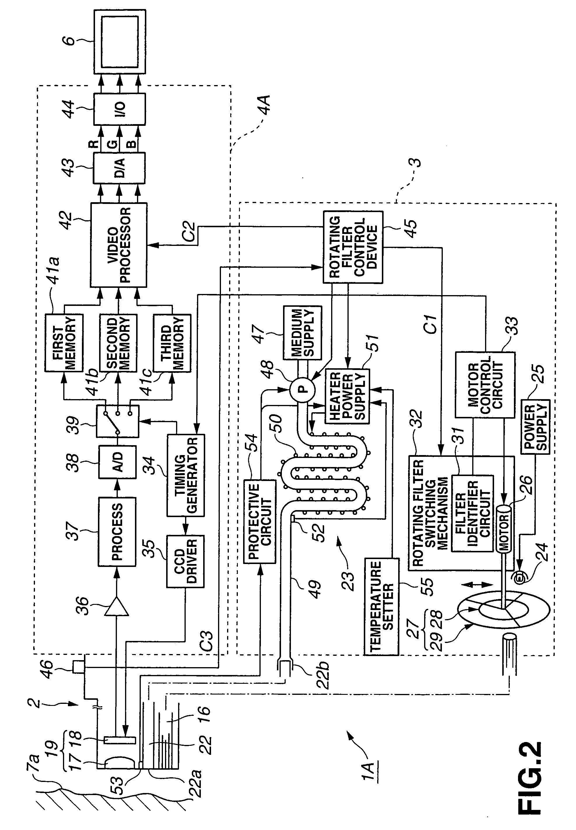
[0043]FIGS. 1 through 11 are related to a first embodiment of the present invention. FIG. 1 illustrates the entire configuration of an endoscopic apparatus of the present invention, FIG. 2 is a block diagram illustrating in detail the endoscopic apparatus of FIG. 1, FIG. 3 illustrates the configuration of two filter sets provided to a rotating filter, FIG. 4 illustrates spectral characteristics of each filter forming two filter sets of FIG. 3, FIG. 5 is a block diagram illustrating a video processor, and FIG. 6 illustrates operation of the present embodiment.

[0044]FIG. 7 diagrammatically illustrates operation of an NBI observation mode in the first embodiment, FIG. 8 diagrammatically illustrates a display example of a monitor screen which is shown when a mucous membrane is observed, FIG. 9 illustrates transmission characteristics of a filter set of a first modification for use in the NBI observation mode, FIG. 10 illustrates transmission characteristics of the filter set of a second...

second embodiment

[0154]Referring to FIG. 12, a second embodiment of the present invention is described below. FIG. 12 diagrammatically illustrates the configuration of an endoscopic apparatus 1C in accordance with the second embodiment of the present invention.

[0155]In accordance with the first embodiment, the thermal medium feeder 23 is arranged in the light source 3, and the thermal medium from the thermal medium feeder 23 is passed through the tubular passage 22 in the electronic endoscope 2 and then sprayed to the observation area. In contrast, the endoscopic apparatus 1C includes in a light source 3B a thermal medium feeder 23B, the medium of which is not yet heated, and a heater in the tubular passage 22 in an electronic endoscope 2C. The heated medium is sprayed from the distal end opening 22a of the tubular passage 22.

[0156]The thermal medium feeder 23B of FIG. 12 does not include the heater 50 and the heater power supply 51 of FIG. 2.

[0157]Meanwhile, the tubular passage 22 in the electronic...

third embodiment

[0166]A third embodiment of the present invention is described below with reference to FIG. 13. FIG. 13 diagrammatically illustrates the configuration of a major portion of an endoscopic apparatus 1D of the third embodiment of the present invention. In accordance with the third embodiment, a medium, such as a thickener, changing viscosity thereof with temperature is used.

[0167]An electronic endoscope 2D sprays, from the distal end thereof, a medium in a liquid state to the observation area such as the living mucous membrane 7a. The sprayed medium has the function of raising the surface and near-surface region of the observation area in temperature, thereby increasing the blood flow. In addition to this function, the medium shifts to a large viscosity state when the medium drops in temperature, and tends to stay on the observation area. The medium thus has the function of covering the surface of the observation area and maintaining temperature (temperature insulation).

[0168]The endos...


PUM


Abstract

An endoscope includes an insert section to be inserted into the body cavity, an illumination window for directing illumination light therethrough and an observation window for observing an illuminated internal portion of the body cavity, arranged at a distal end portion of the insert section, and a blood flow changing section for changing a blood flow of blood flowing through a vessel in a near-surface region of a living organ inside the body cavity by providing one of a temperature change and vibration energy.

Description

BACKGROUND OF THE INVENTION[0001]1. Field of the Invention[0002]The present invention relates to an endoscope to be inserted in a body cavity appropriate for observing vessels, an endoscopic apparatus, and an examination method of using the endoscope.[0003]2. Description of the Related Art[0004]Recently, endoscopes have been widely used in the medical field. Surgeons use the endoscopes to find and examine a lesion.[0005]For example, cancers, as an example of lesion, tend to develop and cluster in vessels including a capillary vessel in a near-surface region of a living organ. Using an endoscope, a surgeon determines the presence or absence of a capillary vessel in the near-surface layer of the living organ and observes a network of the capillary vessel using the endoscope. The use of the endoscope in this way is becoming an effective method to determine whether a lesion is a cancer.[0006]Thus, observing vessels containing capillary vessels in the near-surface layer of the living org...

Claims


Application Information

Patent Timeline
Patent Type & Authority Applications(United States)
IPC IPC(8): A61B1/12A61B18/18A61N5/06A61B1/06
CPCA61B1/0008A61B1/015A61B1/0638A61B1/12A61B1/0684A61N2005/066A61B1/0646A61B1/0676A61B5/0261A61F7/007A61F7/12A61F2007/0059A61F2007/0086A61B1/00097A61B1/0655
Inventor GONO, KAZUHIROGONO, TAKAAKISHINKAI, NARUTO
Owner OLYMPUS CORP
Why Eureka
Try Eureka