Intraoperative and post-operative adjustment of an annuloplasty ring

a technology of annuloplasty and ring, which is applied in the field of intraoperative and post-operative adjustment of annuloplasty rings, can solve the problems of ineffective closure of valve leaflets, insufficient valve leaflets, and blood circulation affecting the effect of the valve,

Inactive Publication Date: 2007-11-29
MICARDIA CORP
View PDF2 Cites 61 Cited by
  • Summary
  • Abstract
  • Description
  • Claims
  • Application Information

AI Technical Summary

Benefits of technology

[0023] For purposes of summarizing the invention, certain aspects, advantages and novel features of the invention have been described herein. It is to be understood that not necessarily all such advantages may be achieved in accordance with any particular embodiment of the invention. Thus, the invention may be embodied or carried out in a manner that achieves or optimizes one advantage or group of advantages as taught herein without necessarily achieving other advantages as may be taught or suggested herein.

Problems solved by technology

If the valves of the heart do not function properly, due either to disease or congenital defects, the circulation of the blood may be compromised.
Diseased heart valves may be stenotic, wherein the valve does not open sufficiently to allow adequate forward flow of blood through the valve, and / or incompetent, wherein the valve does not close completely.
Incompetent heart valves cause regurgitation or excessive backward flow of blood through the valve when the valve is closed.
When a heart valve annulus dilates, the valve leaflet geometry deforms and causes ineffective closure of the valve leaflets.
The ineffective closure of the valve can cause regurgitation of the blood, accumulation of blood in the heart, and other problems.
Although the implantation of an annuloplasty ring can be effective, the heart of a patient may change geometry over time after implantation.
Whether the size of the heart grows or reduces after implantation of an annuloplasty ring, the ring may no longer be the appropriate size for the changed size of the valve annulus.

Method used


Image

  • Intraoperative and post-operative adjustment of an annuloplasty ring
  • Intraoperative and post-operative adjustment of an annuloplasty ring
  • Intraoperative and post-operative adjustment of an annuloplasty ring

Examples


Embodiment Construction

Externally Adjustable Annuloplasty Rings

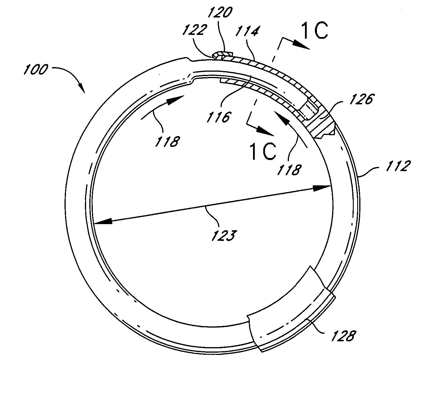
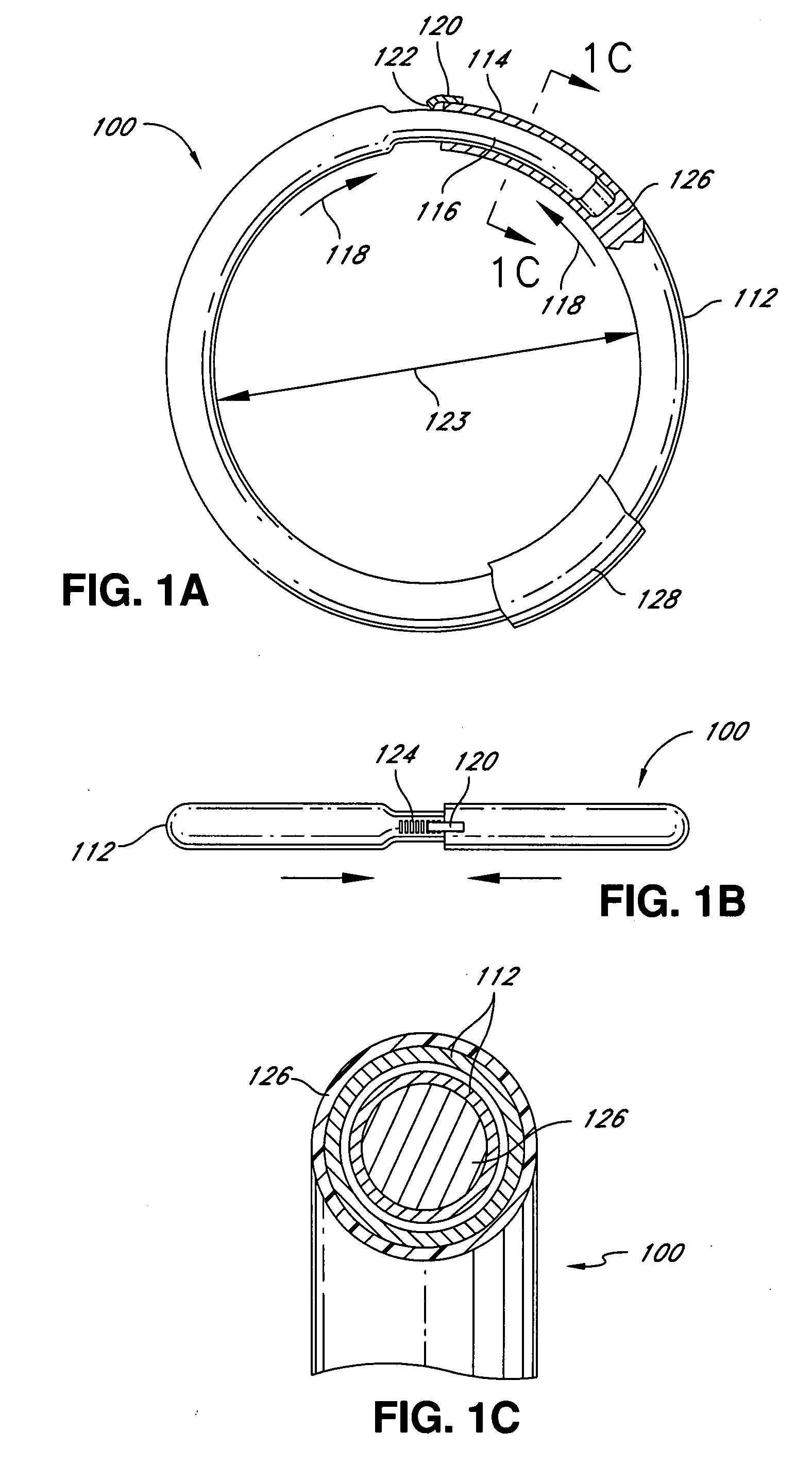
[0085] The present invention involves systems and methods for adjusting adjustable rings and other adjustable implants used for reinforcing dysfunctional heart valves and other body structures. In certain embodiments, such an adjustable annuloplasty ring is implanted into the body of a patient such as a human or other animal. The adjustable annuloplasty ring is implanted through an incision or body opening either thoracically (e.g., open-heart surgery) or percutaneously (e.g., via a femoral artery or vein, or other arteries or veins) as is known to someone skilled in the art. The adjustable annuloplasty ring is attached to the annulus of a heart valve to improve leaflet coaptation and to reduce regurgitation. The annuloplasty ring may be selected from one or more shapes comprising a round or circular shape, an oval shape, a C-shape, a D-shape, a U-shape, an open circle shape, an open oval shape, and other curvilinear shapes.
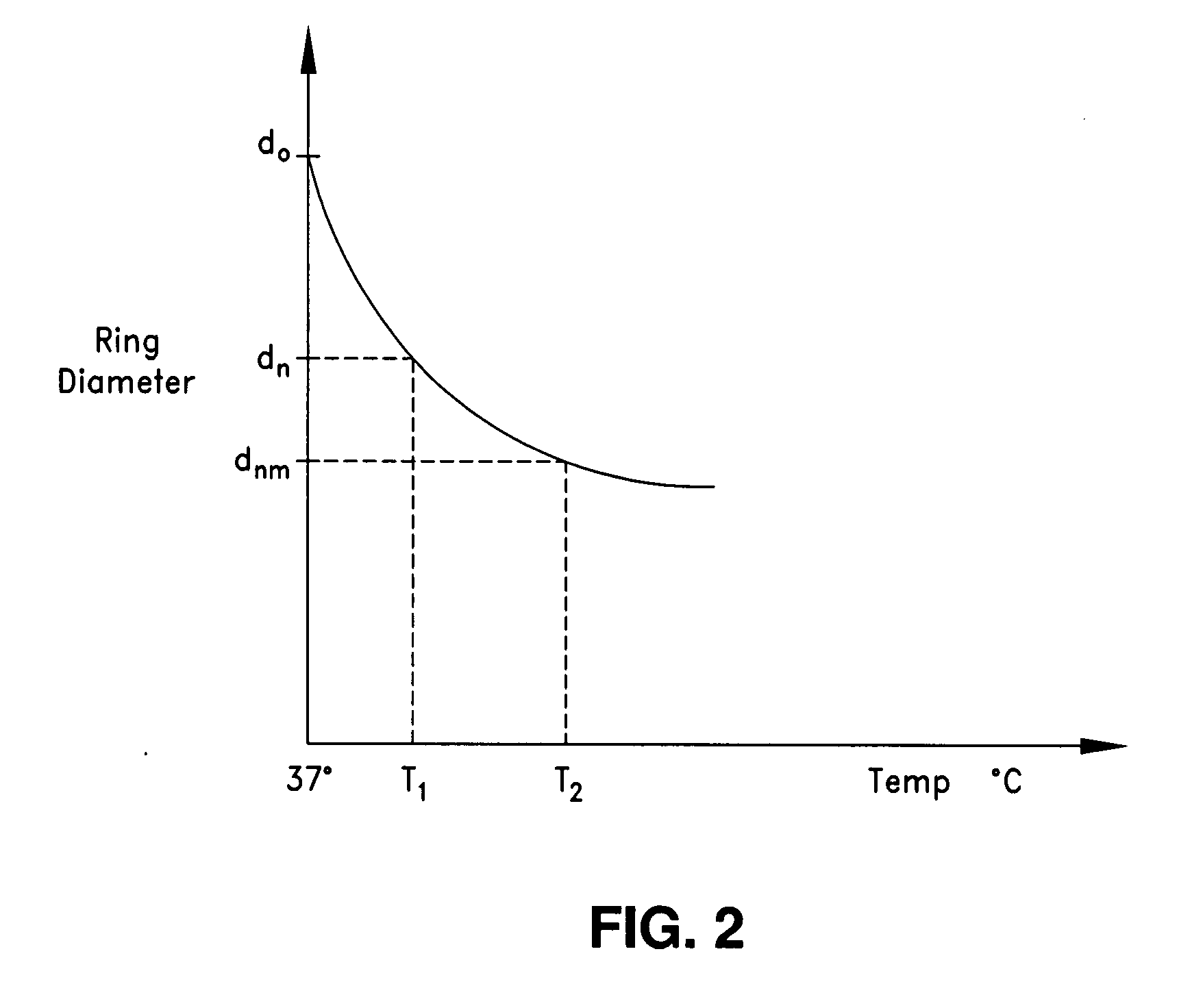
[0086] The size ...


PUM


Abstract

An intraoperative adjustment device is described. In some embodiments, the device includes an elongate body including a proximal end and a distal end, the distal end configured to penetrate an outer surface of an adjustable cardiac implant implanted in a patient's heart, and the proximal end and the distal end connected by at least one energy-transfer member. In some embodiments, the distal end includes at least one electrode coupled to the energy-transfer member and configured to deliver an activation energy to the adjustable cardiac implant. In some embodiments, the proximal end is configured to attach to an energy source that provides the activation energy. In some embodiments, the proximal end is configured to be located outside the patient's body while the distal end is coupled to the adjustable cardiac implant that is implanted in the patient's heart.

Description

CROSS REFERENCE TO RELATED APPLICATIONS [0001] This application claims the benefit of priority under 35 U.S.C. §119(e) of U.S. Provisional Patent Application No. 60 / 799,909, filed on May 12, 2006, and titled “INTRAOPERATIVE AND POST-OPERATIVE ADJUSTMENT OF AN ANNULOPLASTY RING,” the entirety of which is hereby incorporated by reference for all purposes.BACKGROUND OF THE INVENTION [0002] 1. Field of the Invention [0003] The present disclosure relates generally to devices and methods for reinforcing body structures, for example, heart valves, and more particularly, for adjusting an annuloplasty ring intraoperatively. [0004] 2. Description of the Related Art [0005] The circulatory system of mammals includes the heart and the interconnecting vessels throughout the body that include both veins and arteries. The human heart includes four chambers, which are the left and right atrium and the left and right ventricles. The mitral valve, which allows blood flow in one direction, is positione...

Claims


Application Information

Patent Timeline
Patent Type & Authority Applications(United States)
IPC IPC(8): A61F2/24
CPCA61F2/2445A61F2/2448A61F2250/0004A61F2250/0001A61F2210/0038
Inventor MARMUREANU, ALEXANDERLE, LEFLORES, JESUSTRAN, JASONSHAOLIAN, SAMUEL
Owner MICARDIA CORP
Why Eureka
Try Eureka