
Neural network based refrigerant charge detection algorithm for vapor compression systems

a technology of vapor compression system and refrigerant charge detection, applied in the field of aircraft vapor compression system, can solve the problems of reducing the performance of vcs system, difficult refrigerant charge level determination, and typical complex vcs operation

Inactive Publication Date: 2007-12-06
HONEYWELL INT INC
View PDF20 Cites 8 Cited by
  • Summary
  • Abstract
  • Description
  • Claims
  • Application Information

AI Technical Summary

Benefits of technology

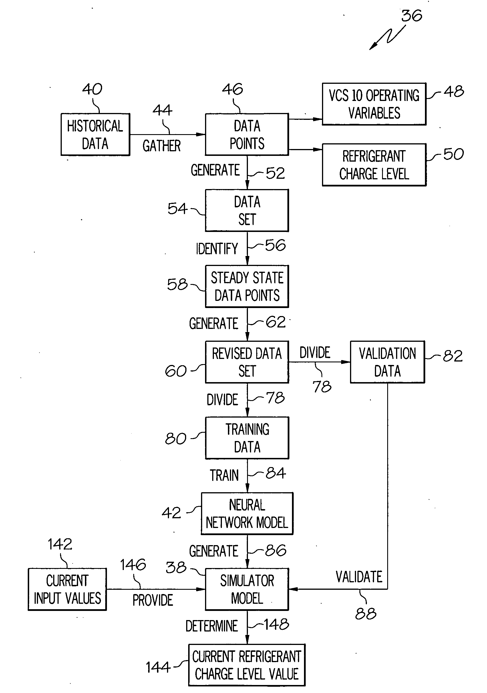
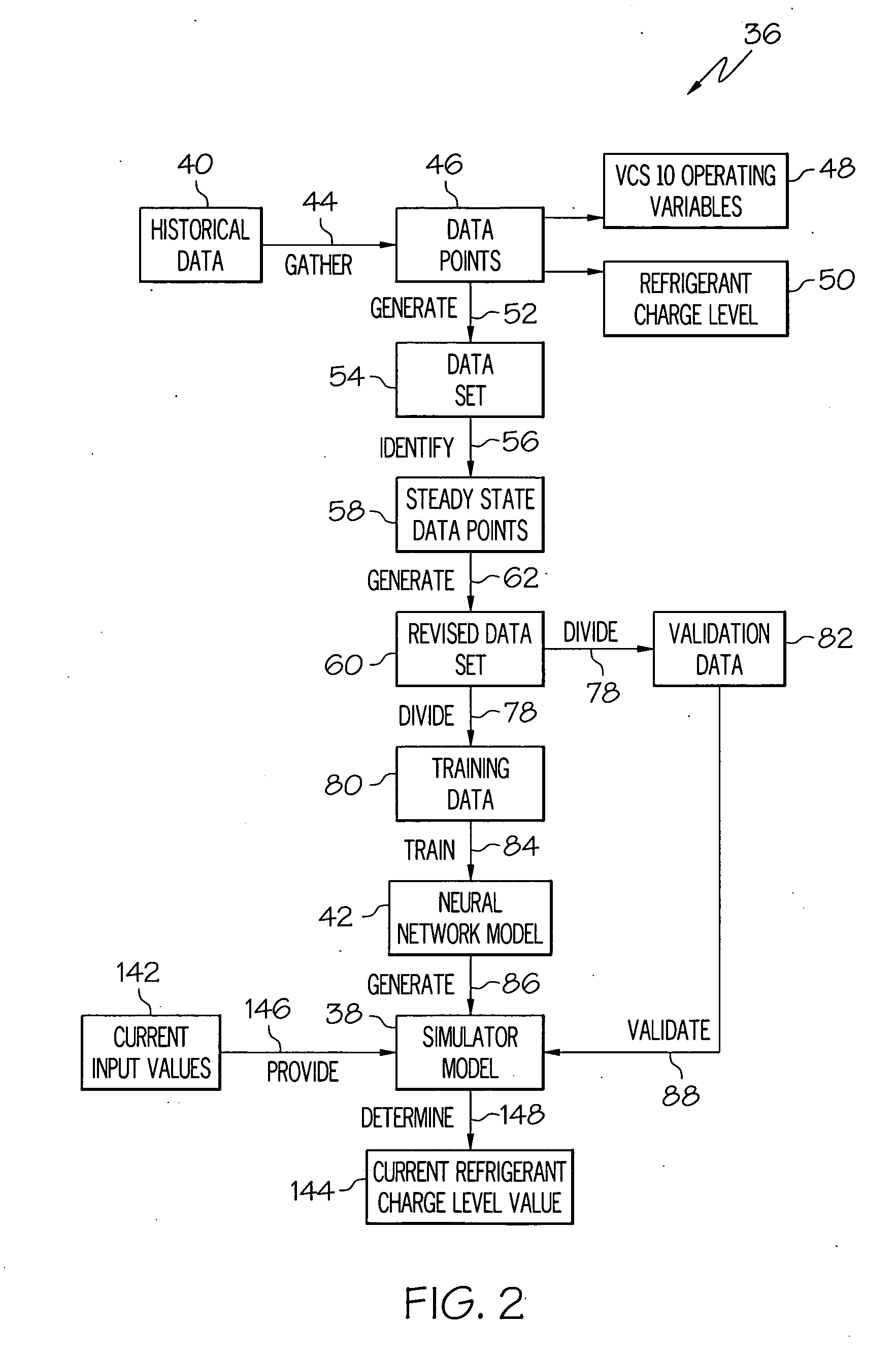
The patent describes a method for determining the refrigerant charge in a vapor compressor system (VCS) of an aircraft using a nonlinear neural network model. The method involves generating a data set from historical data on the operation of the VCS, identifying steady-state data points, and using principal components analysis (PCA) to derive minimally correlated input variables from the VCS operating variables. These input variables are then supplied to a nonlinear neural network model to determine the relationship between them and the refrigerant charge in the VCS. The technical effect of this method is to provide a more accurate and reliable means for determining the refrigerant charge in the VCS of an aircraft.

Problems solved by technology

A low refrigerant charge level can result in decreased VCS system performance, particularly at higher heat loads.
However, the determination of refrigerant charge level can be difficult.
This difficulty arises because the VCS operation is typically complex, with many interacting control loops.
However, such methods to date have provided less than optimal results, for example due to a lack of a sufficient number of input variables, and / or due to substantial collinearity among input variables.

Method used


Image

  • Neural network based refrigerant charge detection algorithm for vapor compression systems
  • Neural network based refrigerant charge detection algorithm for vapor compression systems
  • Neural network based refrigerant charge detection algorithm for vapor compression systems

Examples


Embodiment Construction

[0024]The following detailed description of the invention is merely exemplary in nature and is not intended to limit the invention or the application and uses of the invention. Furthermore, there is no intention to be bound by any theory presented in the preceding background of the invention or the following detailed description of the invention.

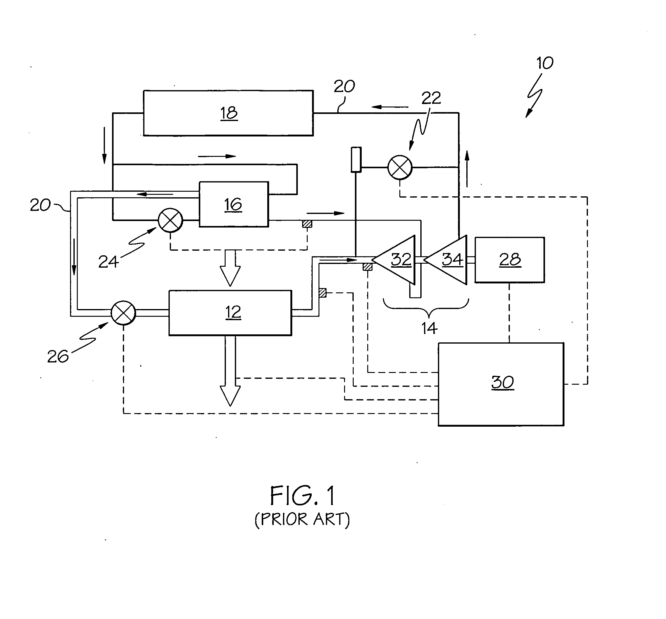
[0025]FIG. 1 depicts an embodiment of a known vapor compression system (VCS) 10 for aircraft. The depicted VCS 10 has an evaporator 12, a compressor 14, a flash subcooler 16, a condenser 18, refrigerant lines 20, a surge valve 22, a thermal expansion valve 24, and a refrigerant expansion valve 26. The VCS 10 components are operated by a motor 28 and a controller 30.

[0026]In conditions requiring maximum cooling, refrigerant enters the evaporator 12 as a low-temperature mixture of liquid and vapor, and flows through the evaporator 12. In this section of the VCS 10, which is generally referred to as the low-pressure side, the pressure remains e...


PUM

PropertyMeasurementUnit
temperatureaaaaaaaaaa
outlet temperatureaaaaaaaaaa
inlet temperatureaaaaaaaaaa

Abstract

Methods and apparatus are provided for determining refrigerant charge in a vapor compressor system (VCS) of an aircraft. The methods and apparatus comprise the following steps of, and / or means for, generating a data set from historical data representative of a plurality of VCS operating conditions over time, identifying one or more steady-state data points in the generated data set, forming a revised data set that includes at least the steady-state data points, using principal components analysis (PCA) to derive values for a plurality of minimally correlated input variables, supplying the derived values for the plurality of minimally correlated input variables and the corresponding values for the VCS refrigerant charge in the revised data set to a nonlinear neural network model, and deriving a simulator model characterizing a relationship between the plurality of minimally correlated input variables and the VCS refrigerant charge.

Description

TECHNICAL FIELD[0001]The present invention generally relates to vapor compression systems for aircraft, and more particularly relates to a method and apparatus for determining refrigerant charge in a vapor compression system.BACKGROUND[0002]Vapor compression systems (VCS) in aircraft are used to supply refrigerant cooled air, which is used primarily for cooling avionic systems. The VCS is generally a closed-loop system, and may include a ram-air cooled condenser, an evaporator with a draw through fan, a centrifugal compressor driven by an electric motor, and a flash subcooler heat exchanger to improve overall system efficiency.[0003]A low refrigerant charge level can result in decreased VCS system performance, particularly at higher heat loads. It may thus be appreciated that it is generally desirable to determine refrigerant charge level. However, the determination of refrigerant charge level can be difficult. This difficulty arises because the VCS operation is typically complex, w...

Claims


Application Information

Patent Timeline
Patent Type & Authority Applications(United States)
IPC IPC(8): G01K13/00F25B45/00
CPCB64D13/06B64D2013/0614B64D2013/0644Y02T50/56F25B49/005F25B2500/19F25B2600/05B64D2013/0674Y02T50/50
Inventor PARTHASARATHY, GIRIJALEM, LAWRENCE A.HOSLER, BRIAN G.MENON, SUNIL K.
Owner HONEYWELL INT INC
Learn More