Flexible connector

a connector and flexible technology, applied in the field of connectors, can solve the problems of affecting the seal formation, prior art connectors failing to provide the flexibility necessary to account, etc., and achieve the effect of preventing the disruption of the seal

Active Publication Date: 2007-12-06
PHILIPS RS NORTH AMERICA LLC
View PDF63 Cites 125 Cited by
  • Summary
  • Abstract
  • Description
  • Claims
  • Application Information

AI Technical Summary

Benefits of technology

[0009] Accordingly, the present invention provides a flexible connector for a pressure support system that addresses the above-identified concerns and that overcomes shortcomings of conventional connectors and / or patient interface devices. The flexible connector of the present invention prevents disruption of the seal between the patient interface device and the patient's face. The flexible connector may have a swivel portion. The flexible connector may have a bellows portion with a longitudinally directed portion, a narrowed neck portion, or a plurality of corrugations. The present invention further provides a system for delivering a flow of gas to a patient that addresses the above identified concerns and that does not suffer from the shortcomings of conventional systems. This is achieved by providing a system for delivering a flow of gas to a patient that includes a gas flow generating device capable of producing a flow of gas and a conduit having a first end portion operatively coupled to the gas flow generating device and a second end portion. The conduit carries the flow of gas from the gas flow generating device. The system includes a patient interface device operatively coupled to the second end portion of the conduit via a flexible connector. The patient interface device may be a nasal mask assembly, an oral mask, or mouthpiece, or combination nasal / oral masks.

Problems solved by technology

One concern in such a situation is that movement of the delivery conduit will disrupt the seal which is formed between the mask and the patient's face.
Prior art connectors fail to provide the flexibility necessary to account for this movement.

Method used


Image

  • Flexible connector
  • Flexible connector
  • Flexible connector

Examples


Embodiment Construction

[0032] Directional phrases used herein, such as, for example, left, right, clockwise, counterclockwise, top, bottom, up, down, and derivatives thereof, relate to the orientation of the elements shown in the drawings and are not limiting upon the claims unless expressly recited therein.

[0033] As employed herein, the term “number” shall mean one or more than one and the singular form of “a”, “an”, and “the” include plural referents unless the context clearly indicates otherwise.

[0034] As employed herein, the statement that two or more parts are “connected” or “coupled” together shall mean that the parts are joined together either directly or joined together through one or more intermediate parts. Further, as employed herein, the statement that two or more parts are “attached” shall mean that the parts are joined together directly.

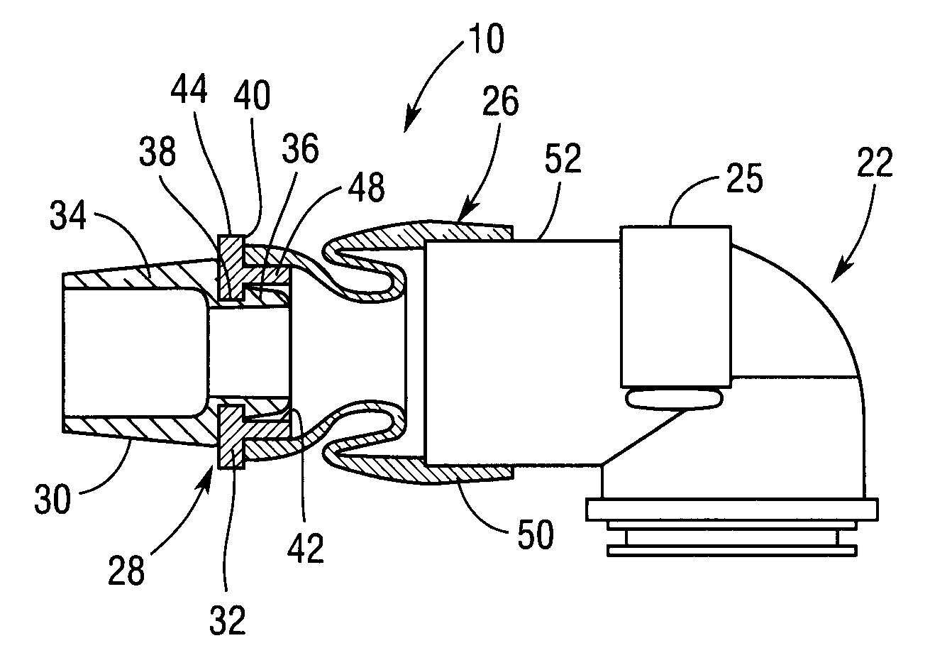
[0035]FIG. 1 illustrates an exemplary embodiment of a system 5 for delivering pressurized breathing gas to a patient. System 5 includes a pressure generat...


PUM


Abstract

A flexible connector that couples a delivery conduit to a patient interface device and a pressure support system that includes such a flexible connector. The flexible connector of the present invention prevents disruption of the seal between the patient interface and the patient's face. The flexible connector may have a bellows portion with a longitudinally directed portion, a narrowed neck portion, or a plurality of corrugations. The flexible connector may further have a swivel portion and/or an exhaust member, and/or a hinge member.

Description

CROSS-REFERENCE TO RELATED APPLICATIONS [0001] This application claims priority under 35 U.S.C. §119(e) from provisional U.S. patent application No. 60 / 811,006 filed Jun. 5, 2006 the contents of which are incorporated herein by reference.BACKGROUND OF THE INVENTION [0002] 1. Field of the Invention [0003] The present invention generally relates to a connector for use in a pressure support system that supplies a flow of gas to the airway of a patient, and, in particular, to a flexible connector that couples a delivery conduit to a patient interface device and to a pressure support system that includes such a flexible connector. [0004] 2. Description of the Related Art [0005] There are numerous situations where it is necessary or desirable to deliver a flow of breathing gas non-invasively to the airway of a patient, i.e., without intubating the patient or surgically inserting a tracheal tube in their esophagus. For example, it is known to ventilate a patient using a technique known as ...

Claims


Application Information

Patent Timeline
Patent Type & Authority Applications(United States)
IPC IPC(8): A62B18/02
CPCA61M16/0683A61M16/08A61M16/0633Y10S128/912A61M16/0816A61M16/0875A61M2205/0216A61M16/0627A61M16/0825
Inventor HO, PETER CHI FAIMATULA, JEROME JR.BUSCH, LANCEANDREWS, DERRICK
Owner PHILIPS RS NORTH AMERICA LLC
Why Eureka
Try Eureka