Baton scabbard military clip

a military clip and baton technology, applied in the field of batons, can solve the problems of difficult user sitting down, closed loop provided on a military belt clip during manufacture, and uncomfortable scabbards for police and military personnel,

Inactive Publication Date: 2007-12-06
ARMAMENT SYST & PROCEDURES
View PDF40 Cites 27 Cited by
  • Summary
  • Abstract
  • Description
  • Claims
  • Application Information

AI Technical Summary

Benefits of technology

[0008] A scabbard for a baton is provided that is attachable to a belt of a user. The scabbard includes a receiver for the baton of the user, a resilient belt c...

Problems solved by technology

The fixed orientation makes police and military scabbards uncomfortable and difficult for a user to sit down.
For example, a closed loop provided on a military belt clip during manufacture would not be removable.
The pro...

Method used


Image

  • Baton scabbard military clip
  • Baton scabbard military clip
  • Baton scabbard military clip

Examples


Embodiment Construction

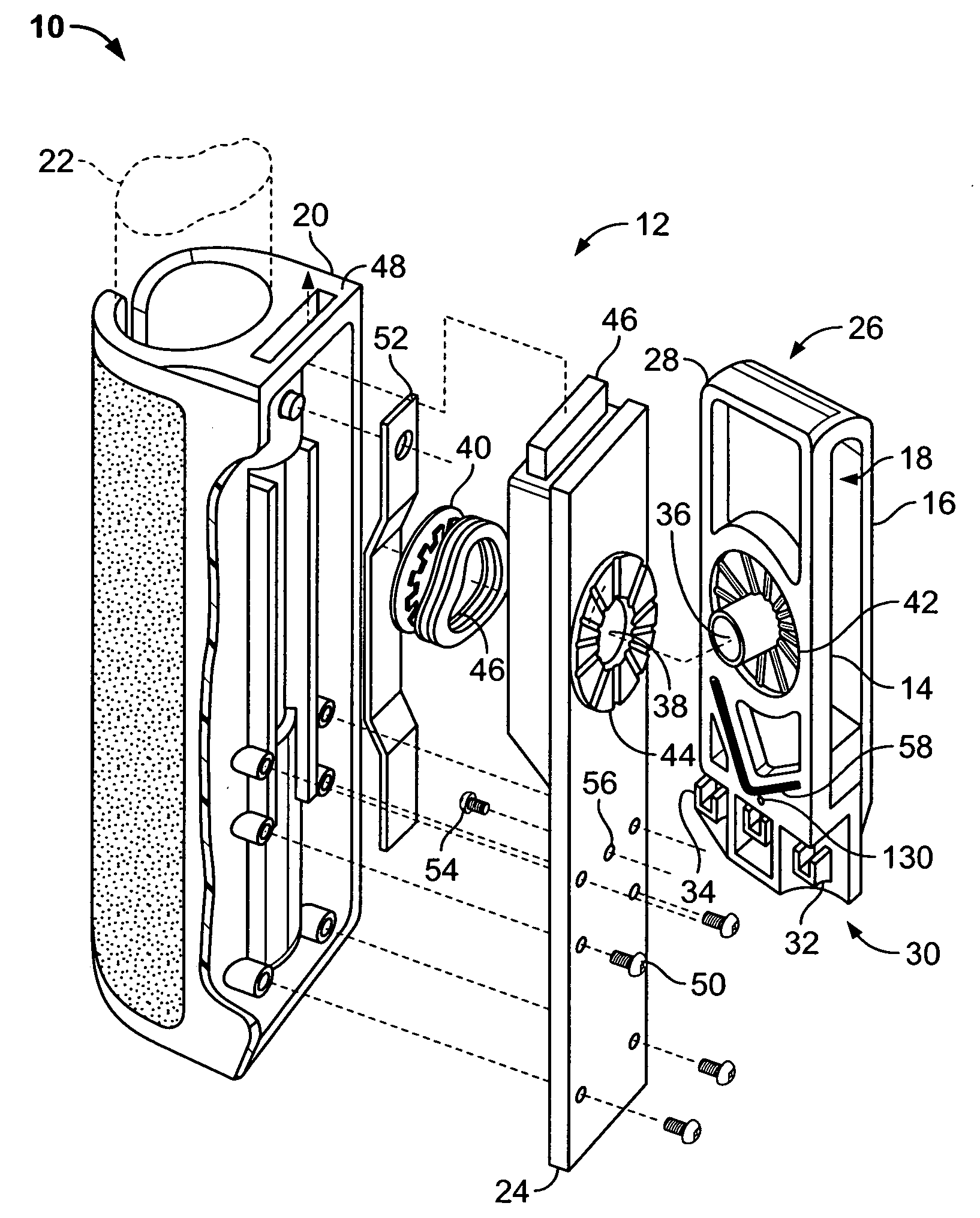
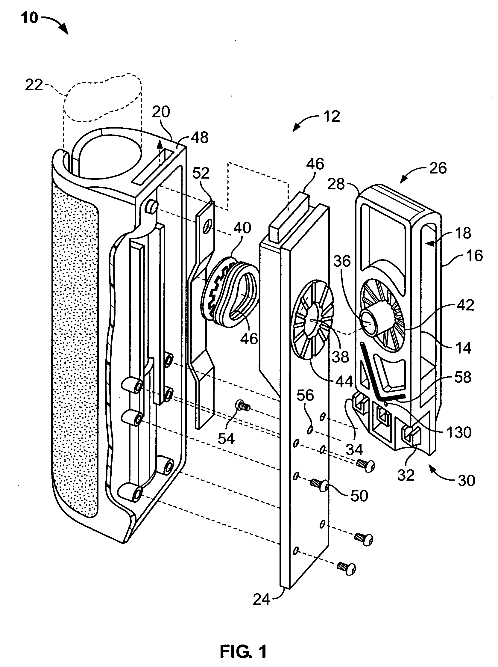
[0018]FIG. 1 is an exploded, side perspective view of a military scabbard 10 shown generally in accordance with an illustrated embodiment of the invention. In general, the scabbard 10 includes a baton receiver 12 and a U-shaped belt clip 26. The belt clip 26 includes a lock 30 that closes off an open end of the U-shaped belt clip 26.

[0019] The belt clip 26 may include a belt attachment plate 28 and a flat clip 16. An inner surface (belt attachment surface) 14 of the belt attachment plate 28 and an inner surface of the resilient flat clip 16 together define a belt passageway 18 for a military belt (not shown) that may be passed through the clip 26 of the scabbard 10.

[0020] The lock 30 positively locks the flat clip 16 to the belt attachment plate 28 to prevent accidental disengagement of the scabbard 10 from the belt of the user. Locking in this case means that the scabbard 10 cannot be removed from the belt of the user without the user intentionally releasing the lock (locking mec...


PUM


Abstract

A scabbard for a baton attachable to a belt of a user. The scabbard includes a receiver for the baton of the user, a resilient belt clip disposed on the receiver and a lock that releasably locks an open end of the belt clip, said lock preventing the belt from being laterally removed from the belt clip.

Description

FIELD OF THE INVENTION [0001] The field of the invention relates to batons and more particularly to scabbards for carrying batons. BACKGROUND OF THE INVENTION [0002] Police officers generally use some sort of scabbard for carrying batons. Such scabbards usually include a cylindrical receptacle that receives the baton and a belt attachment device for attaching the scabbard to a belt of the officer. The cylindrical receptacle may have an open bottom with a restriction that prevents the baton from sliding through the open-bottom. [0003] The belt attachment device used by police is often provided in the form of a closed loop that has a fixed orientation with respect to the receptacle. In order to add or remove a scabbard, a police officer is required remove his belt to attach or detach the scabbard. [0004] Baton scabbards are also used by the military (e.g., military police, peacekeepers, UN missions, etc.). Baton scabbards used by the military also have the fixed orientation between re...

Claims


Application Information

Patent Timeline
IPC IPC(8): A01K97/04
CPCA45F5/02A45F5/021A45F2005/025F41C33/045F41B15/02F41C33/02A45F2200/0566
Inventor PARSONS, KEVIN L.
Owner ARMAMENT SYST & PROCEDURES
Why Eureka
Try Eureka