
Egg counting device and method

a technology of egg counting and counting method, which is applied in the field of egg counting device and method, can solve the problems of independent movement of egg particles and counting errors, and achieve the effects of high resolution, fast counting, and simplified production planning and control

Active Publication Date: 2007-12-06
BIG DUTCHMAN INT
View PDF3 Cites 12 Cited by
  • Summary
  • Abstract
  • Description
  • Claims
  • Application Information

AI Technical Summary

Benefits of technology

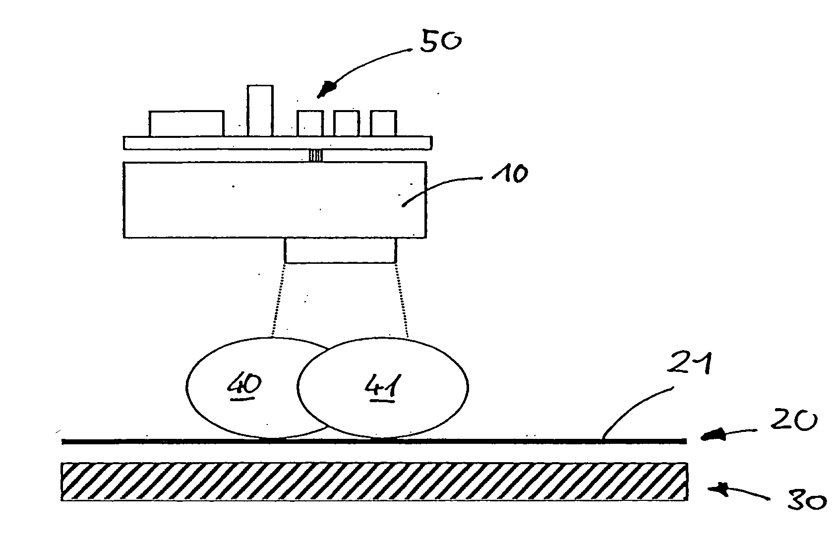
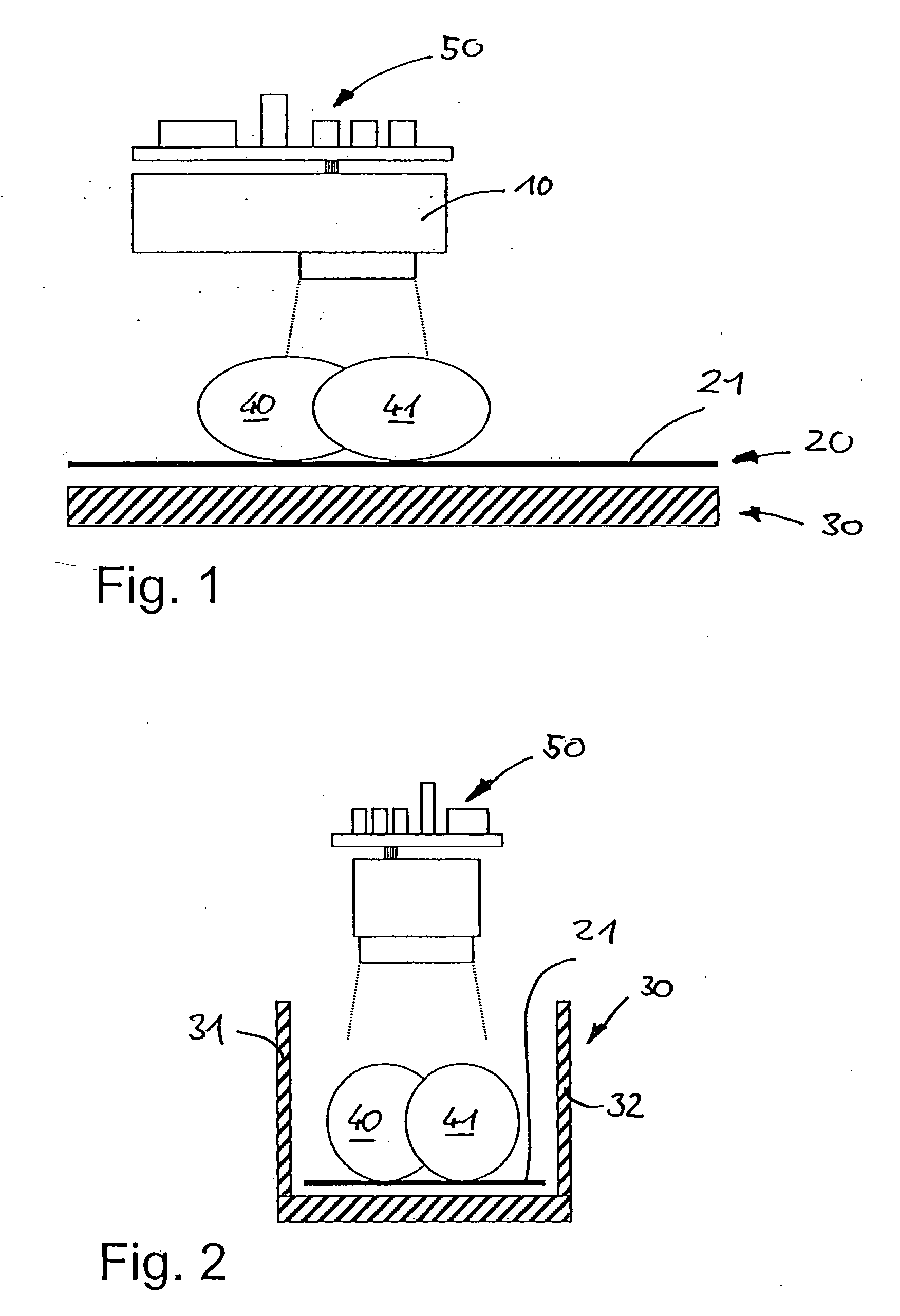
[0010] In one aspect of the present invention, it is possible to establish the movement direction of an object relative to the counting device in a simple and reliable way. For this purpose, the present counting device provides at least one additional row of detectors, which are arranged so that an object to be counted passes through the detection area of the first and second line of detectors with regular relative movement or conveying. The present counting device makes it possible with detection occurring at discrete time intervals with the first and second line for an object to be identified and its outline to be recognized at least partly, and by comparing at least two detections performed at different time intervals, the direction of movement of the object is clearly established. The present counting device is therefore able to count objects reliably, even if the latter move temporarily opposite the actual direction of movement between the counting device and the objects, in that the object cannot only be detected and identified, but the direction of movement of the object can also be established.
[0032] The conveying device makes it possible, in particular in areas in which there is discontinuous production or discontinuous input of products into a conveying device, to control the conveying device as required, i.e., operate the conveying device only when a specific amount of the product has been supplied to the conveying device, which is to be conveyed if necessary for a limited time period.

Problems solved by technology

A problem with conveying objects, particularly round objects, such as eggs, is that the latter can move independently when the conveying device accelerates.
However, the known counting devices are not in a position to differentiate between objects moving in the conveying direction or opposite the conveying direction, so that when there are movements in the wrong direction a counting error occurs.

Method used


Image

  • Egg counting device and method
  • Egg counting device and method
  • Egg counting device and method

Examples


Embodiment Construction

[0040] For purposes of description herein, the terms “upper”, “lower”, “right”, “left”, “rear”, “front”, “vertical”, “horizontal” and derivatives thereof shall relate to the invention as oriented in FIG. 1. However, it is to be understood that the invention may assume various alternative orientations and step sequences, except where expressly specified to the contrary. It is also to be understood that the specific devices and processes illustrated in the attached drawings, and described in the following specification, are simply exemplary embodiments of the inventive concepts defined in the appended claims. Hence, specific dimensions and other physical characteristics relating to the embodiments disclosed herein are not to be considered as limiting, unless the claims expressly state otherwise.

[0041] The embodiment according to the invention comprises a digital, multi-line CCD camera 10, which scans a detection area which extends vertically downward over a prespecified angular area....


PUM


Abstract

A device and related method for counting objects, such as eggs or the like includes a plurality of first detectors, each of which has a locally delimited detection area, which can detect electromagnetic radiation, in particular light in the visible or infrared range, from the detection area, and which are arranged next to one another in a first line. An evaluation unit is coupled to the first detectors and is designed or configured to process the signals of the detectors and on the basis of the signals, to establish the presence of an object in the detection area.

Description

CLAIM OF PRIORITY [0001] Applicant hereby claims the priority benefits under the provisions of 35 U.S.C. § 119, basing said claim of priority on German Patent Application 20 2006 007 875.4, filed May 15, 2006. In accordance with the provisions of 35 U.S.C. § 119 and Rule 55(b), a certified copy of the above-listed German patent application will be filed before the grant of a patent. BACKGROUND OF THE INVENTION [0002] The present invention relates to a device and associated method for counting objects, such as eggs or the like. [0003] Counting objects is necessary in a large number of application areas, for example for controlling production sequences or conveyor processes. The purpose of counting devices or counting methods is to establish the number of individual products that have been produced or are present in a specific time period, in a specific surface area and / or by a specific number of productive units. For this purpose, the products are either guided past a stationary coun...

Claims


Application Information

Patent Timeline
IPC IPC(8): G06M1/10
CPCA01K43/00
Inventor KALKHOFF, CHRISTIAN
Owner BIG DUTCHMAN INT
Learn More