
Controlling delivery of polymer material in a sequential injection molding process

a polymer material and injection molding technology, applied in the direction of auxillary shaping apparatus, manufacturing tools, food shaping, etc., can solve the problems of difficult to achieve such uniform delivery to multiple cavities, difficult to maintain precise control, and difficult to obtain consistency in the precise amount of shots from one cycle to the next, so as to reduce the number of sensors and valve control circuits. , the effect of simplifying the apparatus

Active Publication Date: 2007-12-06
GRAHAM PACKAGING CO LP
View PDF8 Cites 14 Cited by
  • Summary
  • Abstract
  • Description
  • Claims
  • Application Information

AI Technical Summary

Benefits of technology

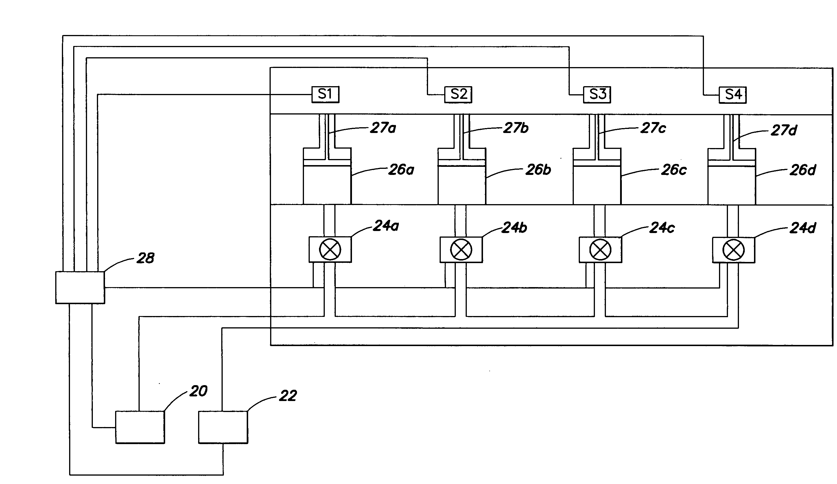
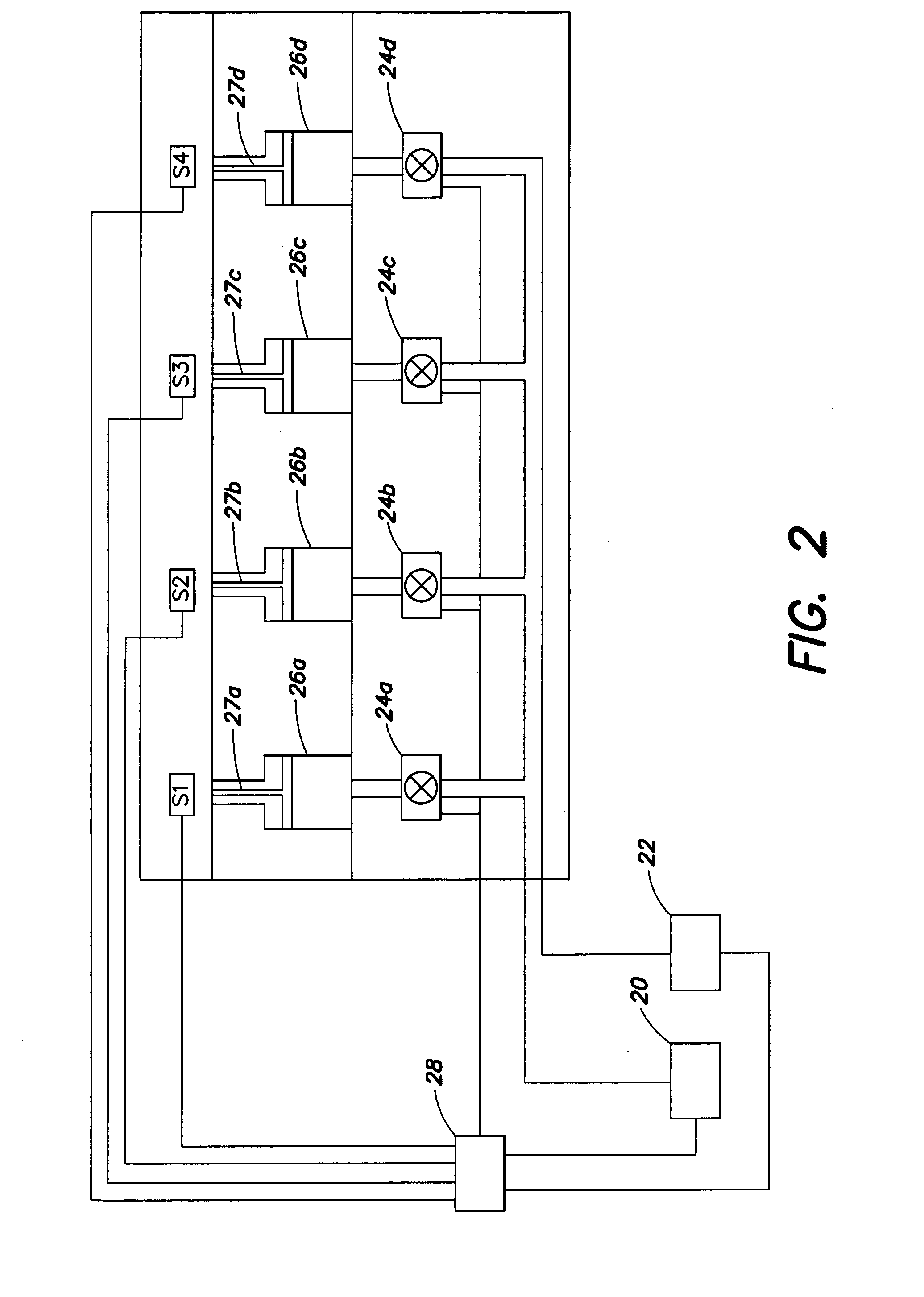
The patent describes a method for delivering multiple shots of material to a mold cavity by sensing a property that is indicative of the volume or flow of material delivered to the cavity during the delivery of the first shot and using the sensed information to control the delivery of the second shot. The method can be used in an injection molding apparatus that has multiple mold cavities and a drive mechanism for delivering the materials to the cavities. The sensors can be placed in the nozzle or in the cavity, and the program uses the sensed information to calculate the volume or flow of material delivered to the cavity during the delivery of the first shot and compare it to a target value to determine if the first shot has achieved the desired volume or flow. The method allows for independent control of the delivery of each material to each cavity and can be used in sequential molding cycles to control the delivery of the first shot.

Problems solved by technology

However, in practice, it is very difficult to achieve such uniform delivery to multiple cavities.
When shots of plastic materials are delivered in sequence to even a single cavity, it can be difficult to obtain consistency in the precise amount of the shots from one cycle to the next.
When shots are routed through multiple flow channels in a hotrunner leading to multiple cavities, it is even more difficult to maintain precise control over the pressure within any given channel or injection nozzle or mold cavity and thus the rate and / or volume of material flow to any particular one of the plurality of cavities will vary.

Method used


Image

  • Controlling delivery of polymer material in a sequential injection molding process
  • Controlling delivery of polymer material in a sequential injection molding process
  • Controlling delivery of polymer material in a sequential injection molding process

Examples


Embodiment Construction

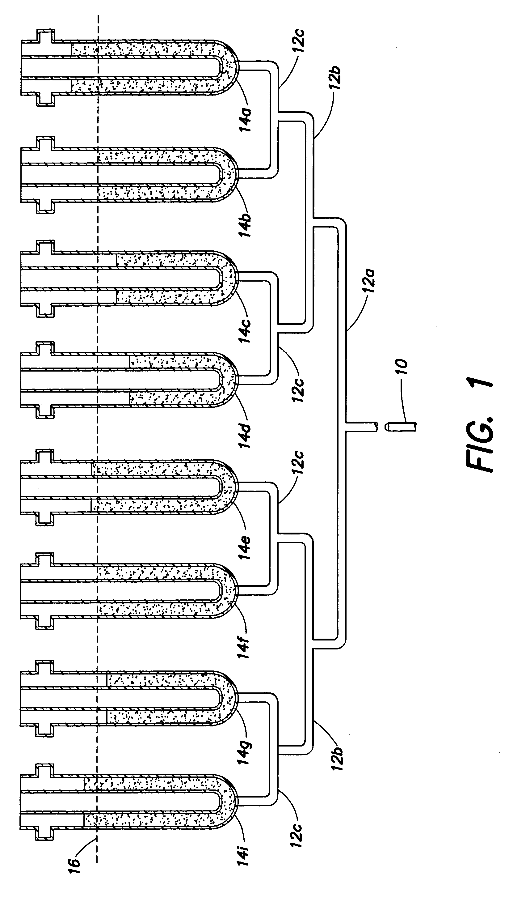
[0052]FIG. 1 shows a mold system having a multiplicity of essentially identically shaped cavities 14a-14i that are fed by a single source of polymer material injection 10. The system shown in FIG. 1 does not include shooting or metering pots to assist in controlling the amount or pressure of material flow to each cavity but rather uses only the single source 10 of injection that provides all of the pressure by which the injected polymer material is forced to flow through all of the various and different manifold channels 12a-12c and into all of the multiple number of cavities 14a-14i. As shown, the forwardmost progress of travel of polymer material into each cavity 14a-14i is different for each cavity, the top or leading edge level of polymer material within each cavity varying in distance either above or below travel line 16 as shown in FIG. 1. These differences in rate and volume of material filling of identically shaped cavities arises out of minor differences in the size, shape,...


PUM

PropertyMeasurementUnit
volumeaaaaaaaaaa
pressureaaaaaaaaaa
temperatureaaaaaaaaaa

Abstract

Method and apparatus for controlling the delivery of polymer material in a sequential injection molding process. In one embodiment, the method provides: delivering a first shot of a first material simultaneously to a plurality of mold cavities; independently sensing for each cavity a property that is indicative of a volume or flow of material that is delivered to the corresponding cavity during the step of delivering the first shot; independently stopping the step of delivering the first shot to one or more cavities according to a program that uses as a variable a signal indicative of the property sensed for the corresponding cavity during delivery of the first shot; and delivering a second shot of a second material simultaneously to the cavities subsequent to the step of stopping the step of delivering the first shot.

Description

FIELD OF THE INVENTION[0001]The present invention relates to controlling one or more of a volume or flow of a first shot of polymer material delivered to a mold in a sequential injection molding process. In a particular embodiment, the invention relates to controlling the simultaneous injection of a first shot of polymer material to a plurality of cavities in a sequential process.BACKGROUND OF THE INVENTION[0002]Injection molding processes for performing sequential shots of different polymer materials are well known. To accomplish such processes, injection molding apparati have been developed using hotrunner systems that are designed to deliver sequential shots of polymer material both to a single cavity and to a plurality of cavities. In multi-cavity applications, shots are intended to be delivered at the same time in the same amounts and at the same rates of flow by controlling the length and configuration of the hotrunner flow channels and the temperature of various portions of t...

Claims


Application Information

Patent Timeline
Patent Type & Authority Applications(United States)
IPC IPC(8): B29C45/76B29C45/17
CPCB29B2911/1406B29K2105/253B29B2911/1408B29B2911/14093B29B2911/1412B29B2911/14126B29B2911/14146B29B2911/14153B29C45/1603B29C45/1643B29C45/1646B29C45/2704B29C45/2725B29C45/2806B29C45/7613B29C2045/1648B29C2045/165B29C2045/2687B29C2045/2722B29C2945/76006B29C2945/76056B29C2945/76107B29C2945/76167B29C2945/76257B29C2945/7628B29C2945/76381B29C2945/76558B29C2945/76591B29C2945/76889B29C2945/76933B29C2945/76939B29B2911/14066B29C2945/76876B29C2949/3009B29C2949/3016B29C2949/302B29C2949/3012B29C2949/303B29C2949/3036B29C2949/3028B29C2949/3038
Inventor NAHILL, THOMAS E.KALMOUNI, SAMMANI, NIKHILBARKER, KEITHLYNCH, BRIAN
Owner GRAHAM PACKAGING CO LP
Learn More